Control system for particulate material drying apparatus and process

a control system and dryer technology, applied in lighting and heating apparatus, furnaces, combustion types, etc., to achieve the effect of easy use and maximum production and efficiency of goods

Active Publication Date: 2006-06-01
RAINBOW ENERGY CENT LLC
View PDF99 Cites 35 Cited by
  • Summary
  • Abstract
  • Description
  • Claims
  • Application Information

AI Technical Summary

Benefits of technology

[0035] One object of the present invention is to allow an electric power plant or other processing plants to maximize the production and efficiency of their goods by utili...

Problems solved by technology

Secondly, the control system controls fluid handl...

Method used


Image

  • Control system for particulate material drying apparatus and process
  • Control system for particulate material drying apparatus and process
  • Control system for particulate material drying apparatus and process

Examples


Embodiment Construction

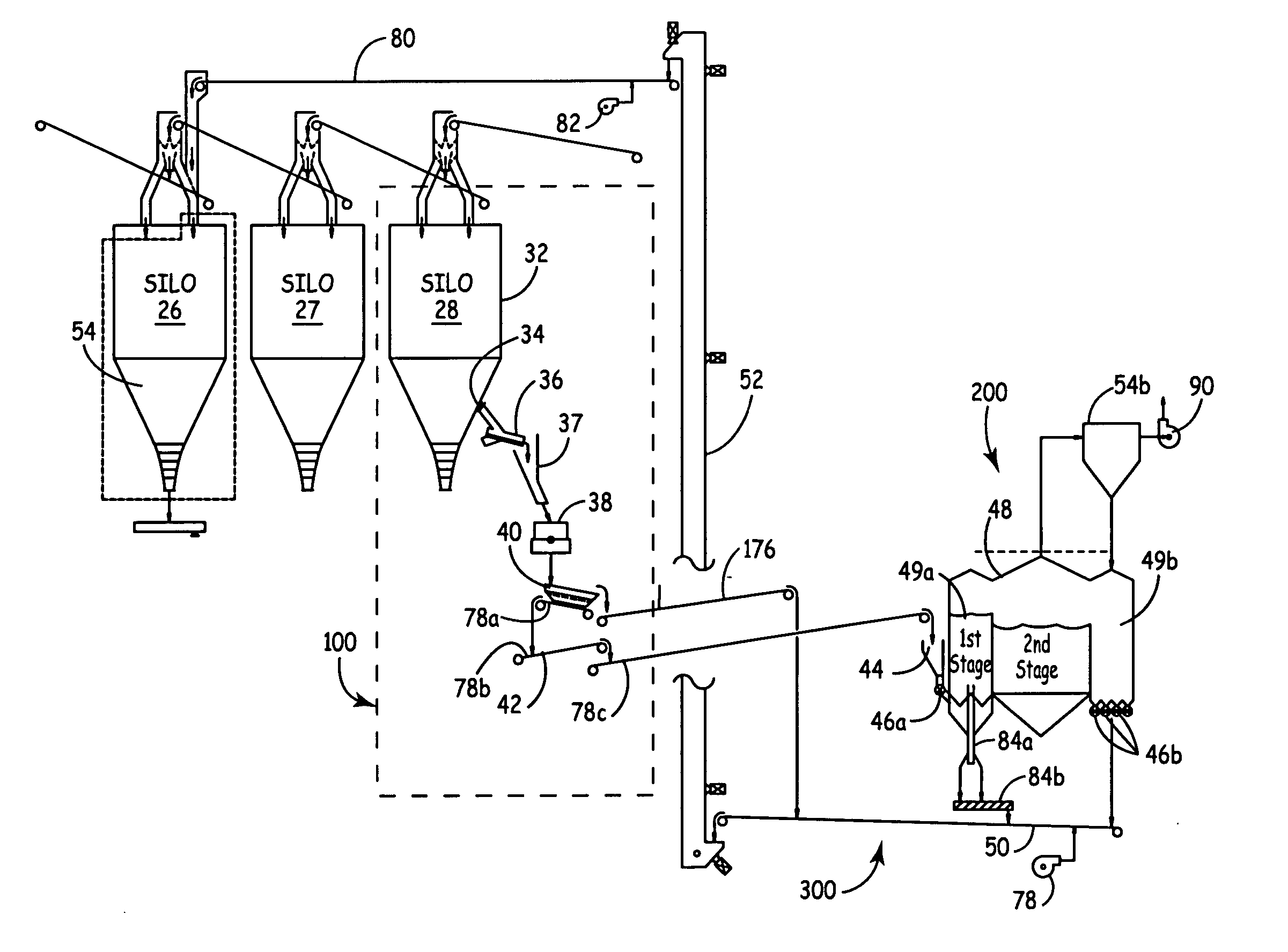
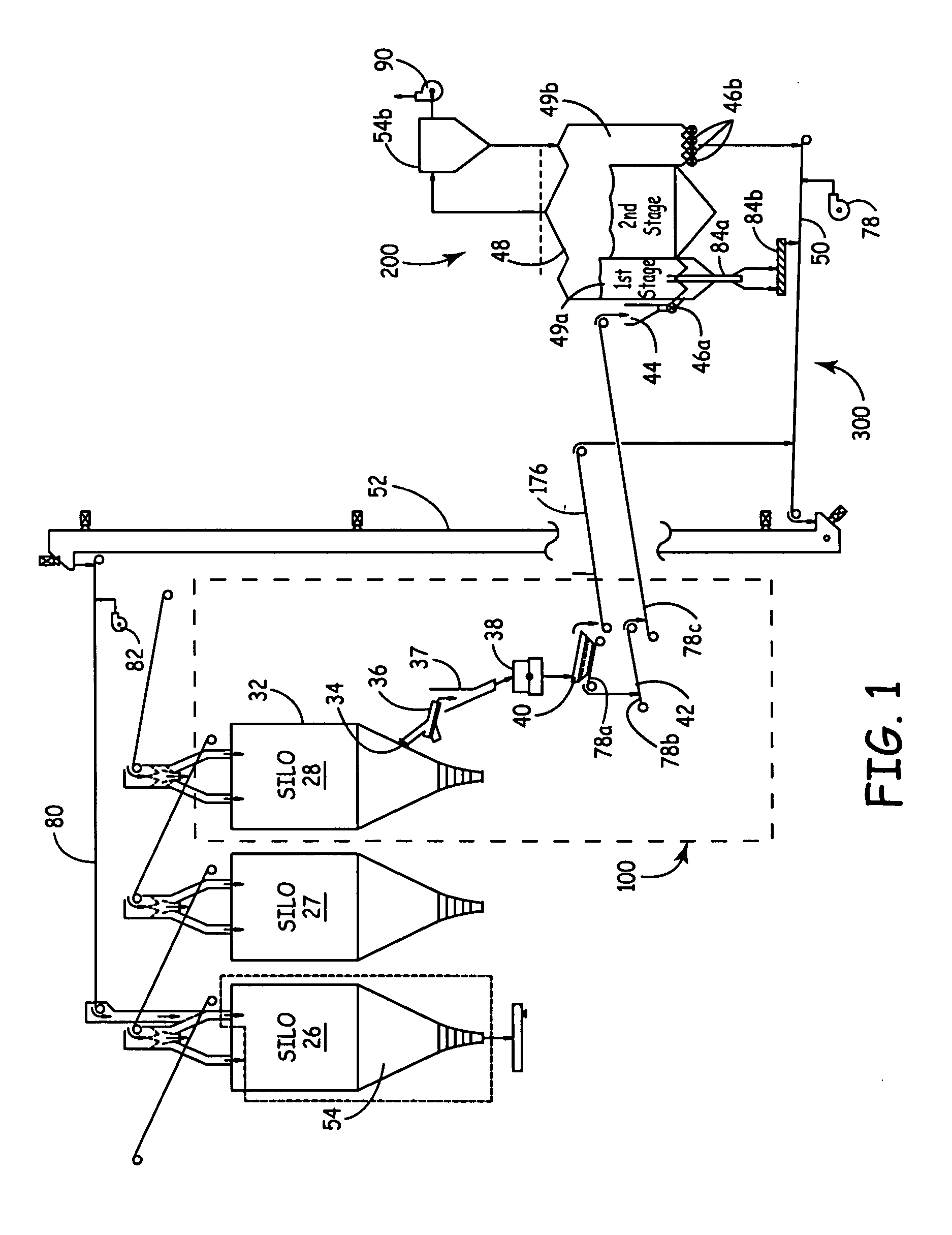
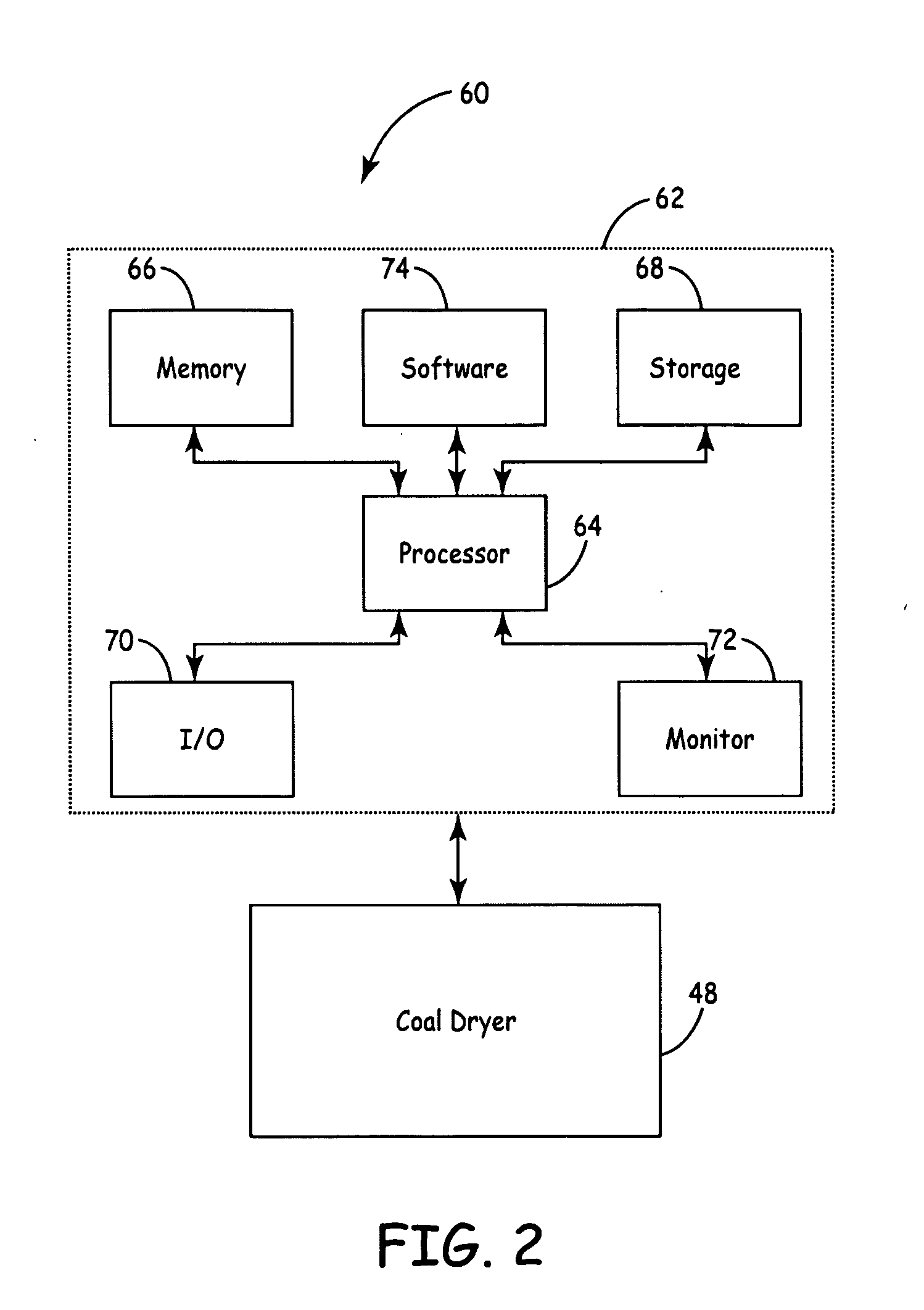
[0047] A control system for controlling the operation of a dryer apparatus for particulate materials within a low-temperature, open-air drying process without plugging in an industrial plant operation is provided by the invention. Such invention allows for the drying of the material on a continuous, higher-throughput, more economical basis, thereby enabling the use of lower-ranked (e.g., higher-moisture) material as a combustion on feedstock source that might not otherwise be viable within an industrial plant operation. Use and control of the dryer apparatus may also enable reduction in pollutants and other undesirable elements contained within the material before it is processed or combusted within the industrial plant operation.

[0048] Although the controller system of the present invention has application to many varied industries, such as food, chemical, and electronic industries, for illustrative purposes, the invention is described herein with respect to a typical coal-burning...


PUM


Abstract

A control system for controlling the utilization of heated waste streams for fluidizing particulate matter such as coal in a fluidizing bed dryer. The control system includes a number of graphic user interfaces that allow an operator to more easily monitor and/or control the various regulator devices. The control system controls coal handling or transportation, fluid handling or flow, and the discharge of discarded or separated coal from the dryer.

Description

CROSS-REFERENCE TO RELATED APPLICATION [0001] This application is a continuation-in-part of U.S. application Ser. No. 11 / 107,152 filed on Apr. 15, 2005, which claims the benefit of U.S. provisional application Ser. No. 60 / 618,379 filed on Oct. 12, 2004, which are hereby incorporated by reference.FIELD OF THE INVENTION [0002] This invention relates to a control system for controlling a dryer apparatus. More specifically, the invention utilizes a general programmable computer system in communication with at least one continuous throughput dryer, such as a fluidized bed dryer, of an industrial processing plant. Additionally, the system is in communication with other functions or operations of the industrial processing plant that are operatively coupled to the throughput dryer. While this system may be utilized in many varied industries in an efficient and economical manner, it is particularly well-suited for use in electric power generation plants for controlling the reduction of moist...

Claims


Application Information

Patent Timeline
IPC IPC(8): F23G5/04F23B90/00F26B3/08F26B3/00
CPCC10L9/08Y02E20/12
Inventor NESS, MARK A.COUGHLIN, MATTHEW P.WHEELDON, JOHN M.JOHNSON, ADAM M.
Owner RAINBOW ENERGY CENT LLC
Why Eureka
Try Eureka