
Controller

a controller and control panel technology, applied in the field of controllers, can solve problems such as poor controllability, large noise, and error against current commands, and achieve the effects of accurate acceleration information, high response, and accurate restrain

Active Publication Date: 2006-06-01
FUJITSU LTD +1
View PDF3 Cites 12 Cited by
  • Summary
  • Abstract
  • Description
  • Claims
  • Application Information

AI Technical Summary

Benefits of technology

[0032] Since there is little noise or phase change, the acceleration detecting means can make correction to restrain vibration of the driven element in accordance with more accurate acceleration information. Since the setting position of the acceleration detecting means can be selected, in particular, the vibration of the driven element can be restrained accurately with high response by locating the detecting means in a position where the vibration of the driven element is expected to be restrained. Further, processing time for the correction can be shortened, since correction processing can be executed with a position / velocity control period longer than a current control period.

Problems solved by technology

If vibration is generated in the driven element, a vibration component in an acceleration signal from the driven element detected by the acceleration sensor causes an error against the current command for the current feedback control.
However, acceleration information that is obtained by differentiating position or velocity information from a position or velocity sensor (or by differentiating the velocity deviation) has problems of much noise and poor controllability.
If a filter is additionally used to remove noise, moreover, phase change that is caused by the filter inevitably worsens the controllability.
Furthermore, there is a problem that the integral of the acceleration information fails to become zero when the driven element returns to its original position after reciprocation under correction control of the current command with the detected acceleration value detected by the acceleration sensor.

Method used


Image

  • Controller
  • Controller
  • Controller

Examples


first embodiment

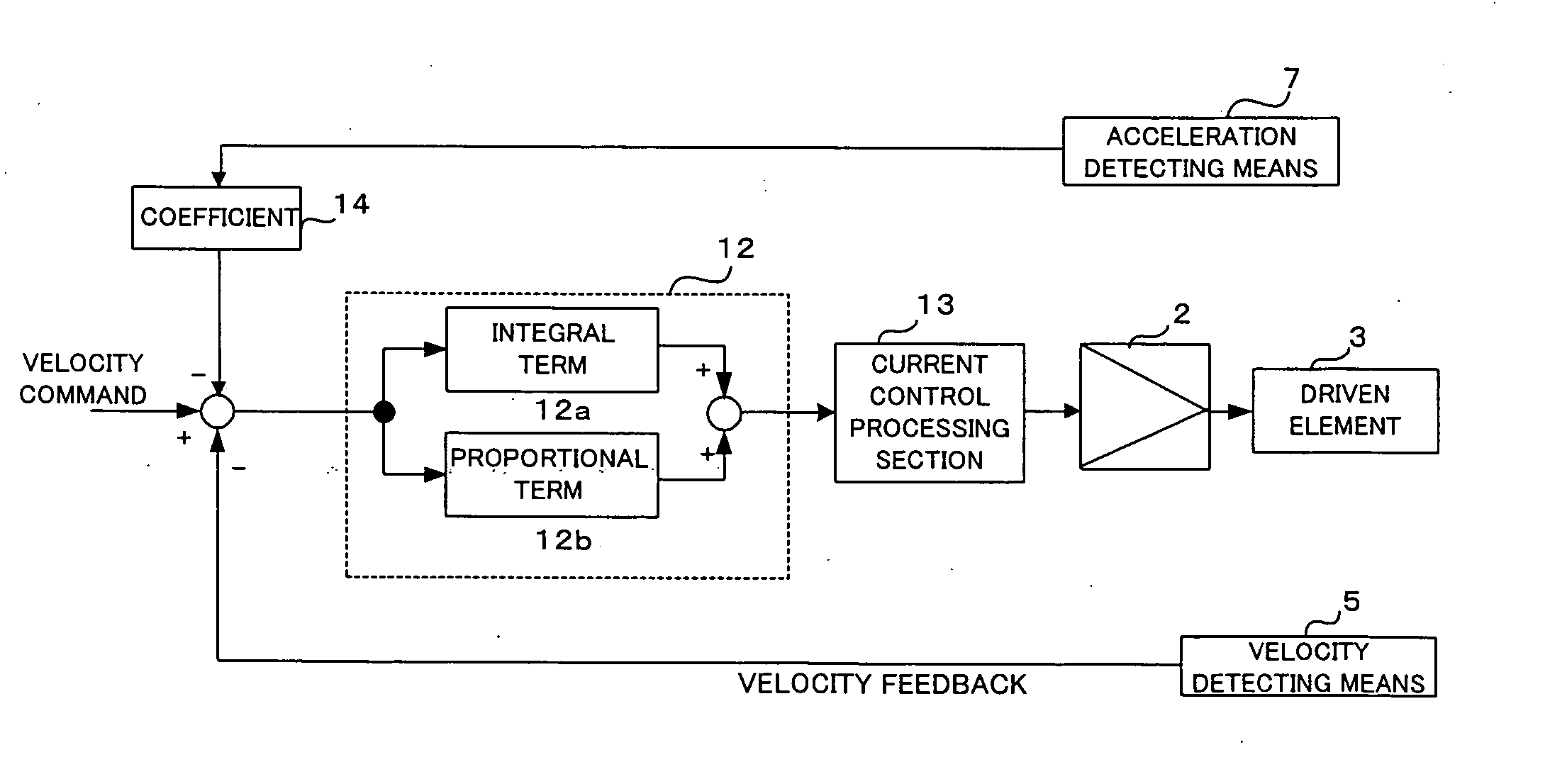
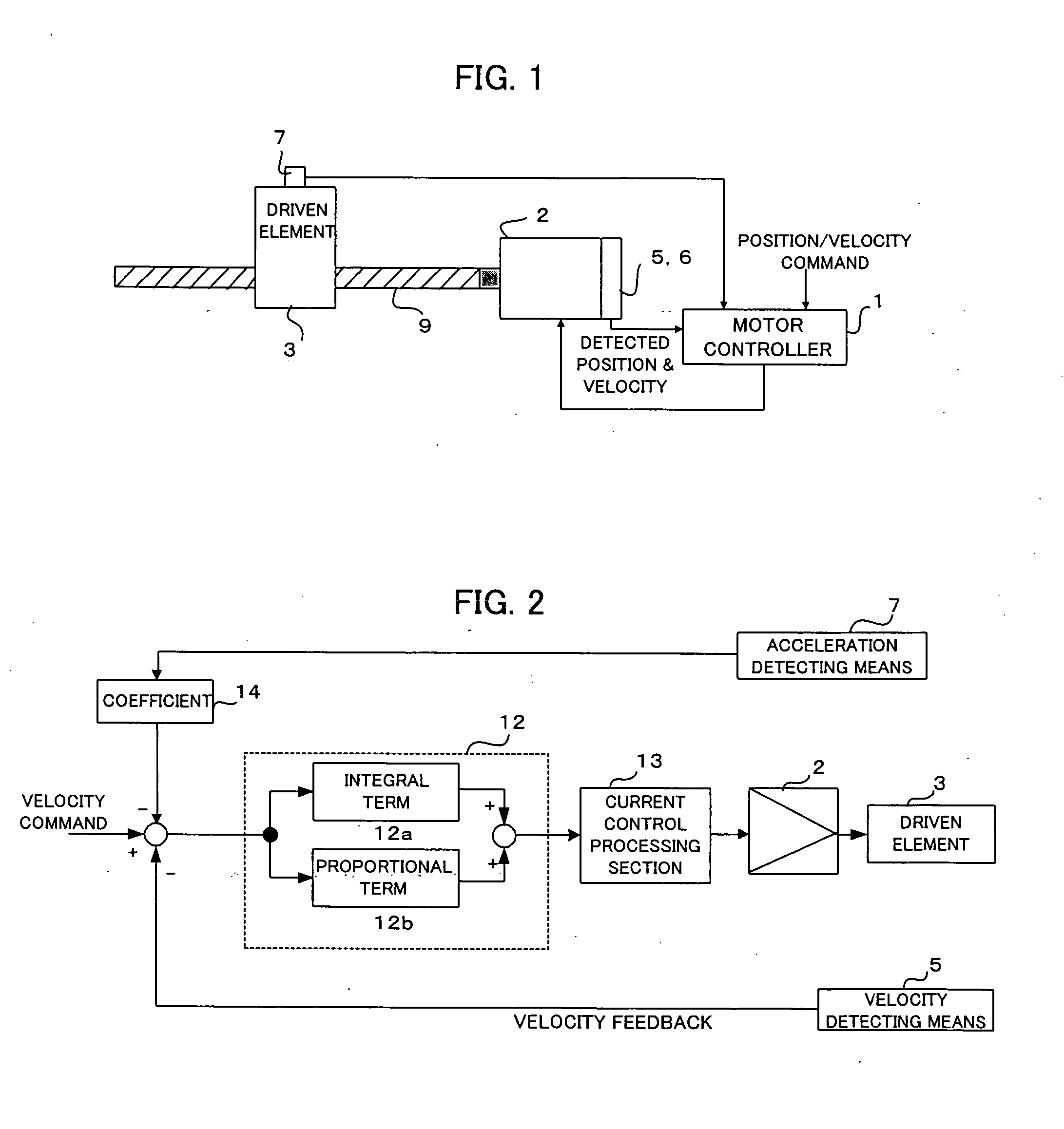
[0058] In the velocity control processing section 12, velocity control processing is executed to obtain a current command in accordance with the command (corrected velocity deviation) inputted in this manner. In the first embodiment shown in FIG. 2, the velocity control is based on PI (proportional plus integral) control with an integral term 12a and a proportional term 12b. Alternatively, however, the control in the velocity control processing section 12 may be composed of IP (integral plus proportional) control or PID (proportional plus integral plus derivative) control. The present embodiment is characterized in that the velocity command is corrected based on the detected acceleration value.

[0059] If the driven element is accelerated suddenly so that the detected acceleration value outputted from the acceleration detecting means 7 increases, the velocity command is reduced by a value obtained by multiplying the detected acceleration value by a coefficient and acts so as to reduce...

third embodiment

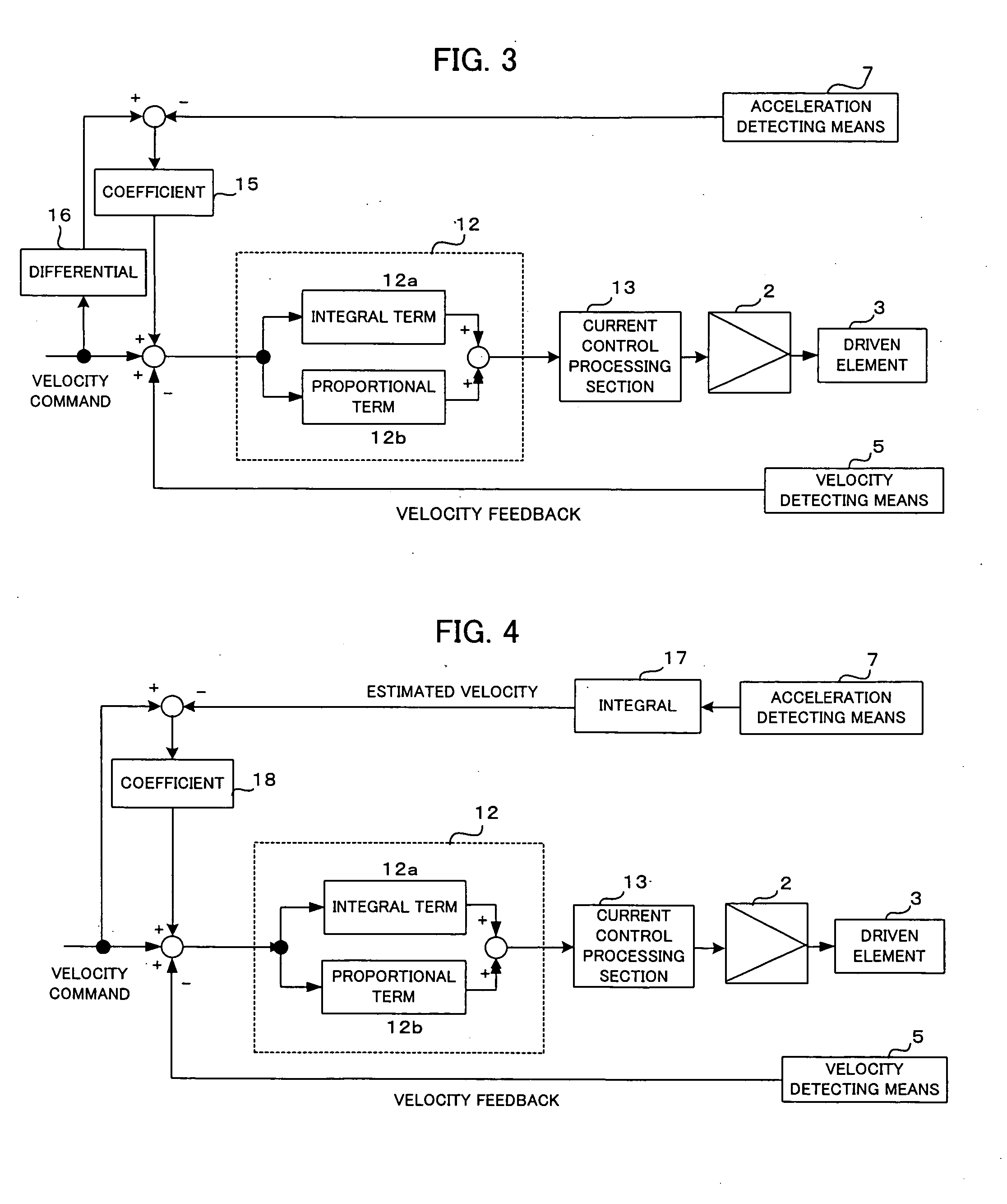
[0064]FIG. 4 is a schematic block diagram showing the present invention.

[0065] This third embodiment is provided with a velocity estimation processing section 17, which integrates a detected acceleration value detected by the acceleration detecting means 7, thereby obtaining an estimated velocity value for correction of a velocity command. A velocity deviation is obtained by subtracting the estimated velocity value obtained by the velocity estimation processing section 17 from the velocity command, and a correction amount is obtained by multiplying the velocity deviation by a coefficient 18. This correction amount is added to the velocity command to correct it or a velocity feedback value. This correction processing is performed together with velocity control processing for each velocity control period. If the control in the velocity control processing section is the PI (proportional plus integral) control or PID (proportional plus integral plus derivative) control, there is no subs...

fourth embodiment

[0067]FIG. 5 is a schematic block diagram showing the present invention.

[0068] This fourth embodiment is provided with a velocity estimation processing section 17, which integrates a detected acceleration value detected by the acceleration detecting means, thereby obtaining an estimated velocity value. The velocity control processing section 12 performs velocity control processing using the product of a coefficient 19 and the estimated velocity value obtained by the velocity estimation processing section 17 as a velocity feedback value. In this case, no velocity detecting means is needed.


PUM


Abstract

Disclosed is a controller for restraining vibration of a driven element driven by a servomotor. The driven element driven by the servomotor is provided with acceleration detecting means. A correction value is obtained by multiplying a detected acceleration value detected by the acceleration detecting means by a coefficient. Correction is made by subtracting the correction value from a velocity command, and velocity feedback control is executed in a velocity control processing section to obtain a current command. Further, the servomotor is driven by current control processing, whereupon the driven element is moved. If the detected acceleration value is increased by vibration of the driven element, the velocity command is corrected to restrain the vibration, so that the vibration of the driven element can be restrained. Processing time can be shortened to restrain the vibration of the driven element by executing the correction of the velocity command based on the detected acceleration value for each velocity control period.

Description

BACKGROUND OF THE INVENTION [0001] 1. Field of the Invention [0002] The present invention relates to a controller for drivingly controlling a servomotor in a machine tool, and more particularly, to a controller configured so that acceleration detecting means is provided on the machine tool to feed back acceleration information, to thereby stabilize an operation of the machine tool. [0003] 2. Description of Related Art [0004] Normally, position, velocity, and current feedback controls are performed in a machine tool to control the position and velocity of a driven element that is driven by a servomotor. FIG. 16 is a block diagram showing a servo control section for controlling the servomotor. A servomotor 2 or a driven element 3 that is driven by the servomotor 2 is provided with velocity detecting means 5 and position detecting means 6 for detecting its velocity and position, respectively. Further, it is provided with current detecting means 4 for detecting the value of a current fo...

Claims


Application Information

Patent Timeline
Patent Type & Authority Applications(United States)
IPC IPC(8): G05D13/00H02P25/098G05D3/12H02P29/00H02P29/40
CPCG05B19/404G05B2219/41117G05B2219/41128G05B2219/42077
Inventor OKITA, TADASHITOYOZAWA, YUKIOKAWAMURA, HIROYUKIIKAI, SATOSHI
Owner FUJITSU LTD
Learn More