Carbon nanotube polymer composition and devices

a technology of carbon nanotubes and polymer compounds, applied in the direction of discharge tubes luminescnet screens, non-metal conductors, applications, etc., can solve the problems of limited materials available, solubility of swnt in other conductive polymer systems,

Active Publication Date: 2006-06-08
RGT UNIV OF CALIFORNIA
View PDF6 Cites 120 Cited by
  • Summary
  • Abstract
  • Description
  • Claims
  • Application Information

AI Technical Summary

Problems solved by technology

Additionally, the use of metals such as calcium, magnesium, or silver blocks useable light from the cathode since they are not transparent and trap the light emissions within the polymer device.
Single wall carbon nanotubes (SVVNT) have been demonstrated to be viable as electron injection material for application in OLEDs.4 However, the applications are limited by the available materials to render the SWNT soluble as well as its compatibility to the light emitting materials.
SWNTs commonly aggregate in solution w...

Method used


Image

  • Carbon nanotube polymer composition and devices
  • Carbon nanotube polymer composition and devices
  • Carbon nanotube polymer composition and devices

Examples


example 1

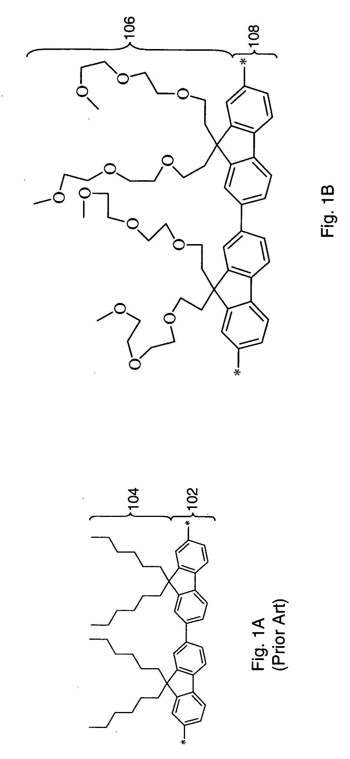
Synthesis of PFO-Poly(2,7-9,9 (di(oxy-2,5,8-trioxadecane))fluorene)

[0059]

Synthesis of 10-Tosyloxy-2,5,8-trioxadecane

[0060] Triethlyene glycol monomethylether (10 g, 61 mmol) was dissolved in THF (50 mL) and cooled to approximately 0° C. in an ice bath. A solution of KOH (5.6 g, 100 mmol) in 10 mL water was slowly added to the mixture, and then a solution of TsCl (9.5 g, 50 mmol) in 20 mL THF was added drop-wise over 20 min. with vigorous stirring. After stirring overnight in an ice bath, the mixture was poured into distilled water (200 mL) and extracted with CH2Cl2 (2×100 mL). The combined organic solutions were washed with saturated NaHCO3 solution (2×100 mL), distilled water (2×100 mL), dried over MgSO4, and concentrated under reduced pressure to give 15.7 g as a clear colorless oil9 in 99% yield. 1H NMR (300 MHz, CDCl3), 2.3 (s, 3H), 3.22 (s, 3H), 3.28-3.70 (m, 10H), 4.04 (t, 2H), 7.24 (d, 2H), 7.68 (d, 2H).

Synthesis of 2,7-Dibromo-9,9 (di(oxy-2,5,8-trioxadecane))fluorene

[006...

example 2

Preparation of a SWNT / PFO

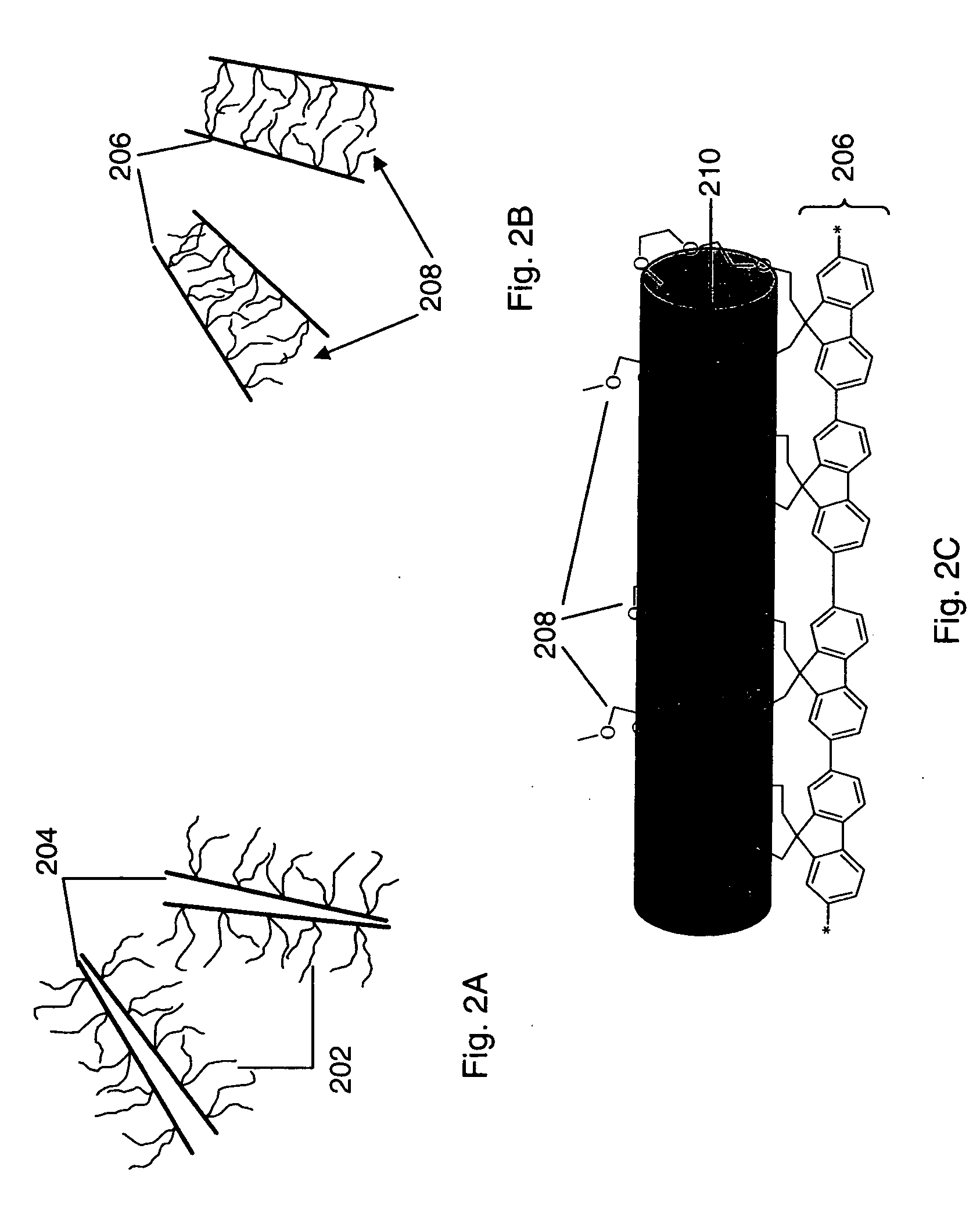
[0063] The as-prepared (AP) grade SWNT tube was purchased from CarboLex® and used without further purification. The AP grade SWNT contains 60% of pure carbon nanotube and 40% of amorphous carbon and catalysts. The dispersion of SWNT is achieved by sonication of the mixture of SWNT, polymer and solution using a Branson 1210 sonicator. The solutions were then left without vibration for a week to sediment. The top part of the solutions was studied and used to cast films.

example 3

Preparation of an OLED with Carbon Nanotube in Light Emitting Layer

[0064] The resistance of the ITO glass used herein is 13 Ω / □. The ITO coated glass was successively cleaned in saturated KOH / Isopropanol solution, followed by three 20-minute sonication cleaning in acetone, isopropanol and methanol and final oxygen plasma treatment. The conductive polymers were spin coated in a class 100 clean room. The PEDOT / PSS aqueous solution was purchased from Aldrich and filtered through a 0.45 μm syringe filter. The PEDOT / PSS layer was spin coated at 1500 rpm, resulting in a 120 nm film. The conductive polymer solutions were filtered with 0.45 μm syringe filter. The generic composition to formulate SWNT / conductive polymer composite is 3.3 g AP grade SWNT / 100 g conductive polymer / 10 L solvent. (3.3 g of AP grade SWNT contains 2 g of pure SWNT). The PFO (or SWNT composite) layer was spin coated at 1000 rpm on the top of PEDOT / PSS layer, resulting in a 40 nm film. 50 nm of aluminum cathode was t...


PUM

PropertyMeasurementUnit
Compositionaaaaaaaaaa
Electrical conductoraaaaaaaaaa
Transport propertiesaaaaaaaaaa

Abstract

A thin film device and compound having an anode, a cathode, and at least one light emitting layer between the anode and cathode, the at least one light emitting layer having at least one carbon nanotube and a conductive polymer.

Description

CROSS-REFERENCE TO RELATED APPLICATIONS [0001] This application claims priority to co-pending provisional application Ser. No. 60 / 634,175 entitled, “Carbon Nanotube Polymer Composition And Devices” filed on Dec. 3, 2004 and is hereby incorporated by reference.STATEMENT OF GOVERNMENTAL SUPPORT [0002] This invention was made with government support under Contract DE-AC02-05CH11231 awarded by the United States Department of Energy to The Regents of the University of California for the management and operation of the Lawrence Berkeley National Laboratory. The government has certain rights in this invention.FIELD OF THE INVENTION [0003] The present invention relates to thin film devices. More particularly, the present invention relates to thin film composition and devices such as organic light emitting devices (“OLEDs”) and organic photovoltaic devices. BACKGROUND OF THE INVENTION [0004] Efficient thin film devices, including organic photovoltaic and organic electroluminescent devices ha...

Claims


Application Information

Patent Timeline
IPC IPC(8): H01B1/00H01L51/46H01L51/54
CPCB82Y10/00H01L51/0049H01L51/0067H01L51/5012Y02E10/549Y10S428/917H10K85/225H10K85/654H10K50/11
Inventor LIU, GAOJOHNSON, STEPHENKERR, JOHN B.MINOR, ANDREW M.MAO, SAMUEL S.
Owner RGT UNIV OF CALIFORNIA
Why Eureka
Try Eureka