Cooling apparatus for vertically stacked printed circuit boards

Active Publication Date: 2006-06-08
LENOVO GLOBAL TECH INT LTD
View PDF20 Cites 74 Cited by
  • Summary
  • Abstract
  • Description
  • Claims
  • Application Information

AI Technical Summary

Benefits of technology

[0009] An apparatus, system and method for cooling vertically stacked printed circuit boards (PCBs) are disclosed herein. In one embodiment, a first PCB is disposed within a substantially enclosed lower chamber inside a PCB containment housing. A second PCB is disposed above the first PCB within the housing to define a substantially enclosed upper chamber above the lower chamber. The second PCB includes one or more airflow apertures defined therethrough

Problems solved by technology

With microelectronics technology steadily increasing integrated circuit (IC) chip density and the density in which such circuits are mounted onto system planar printed circuit boards (PCBs), cooling issues are becoming increasingly critical to design of large-scale data processing systems.
Current requirements for compact, lightweight electronic packages, containing, for example, a large number of closely spaced or stacked electronic circuit boards have not been fully satisfied by existing systems either because such systems provide an insufficient coolant flow to particular components due to such component

Method used


Image

  • Cooling apparatus for vertically stacked printed circuit boards
  • Cooling apparatus for vertically stacked printed circuit boards
  • Cooling apparatus for vertically stacked printed circuit boards

Examples


Embodiment Construction

)

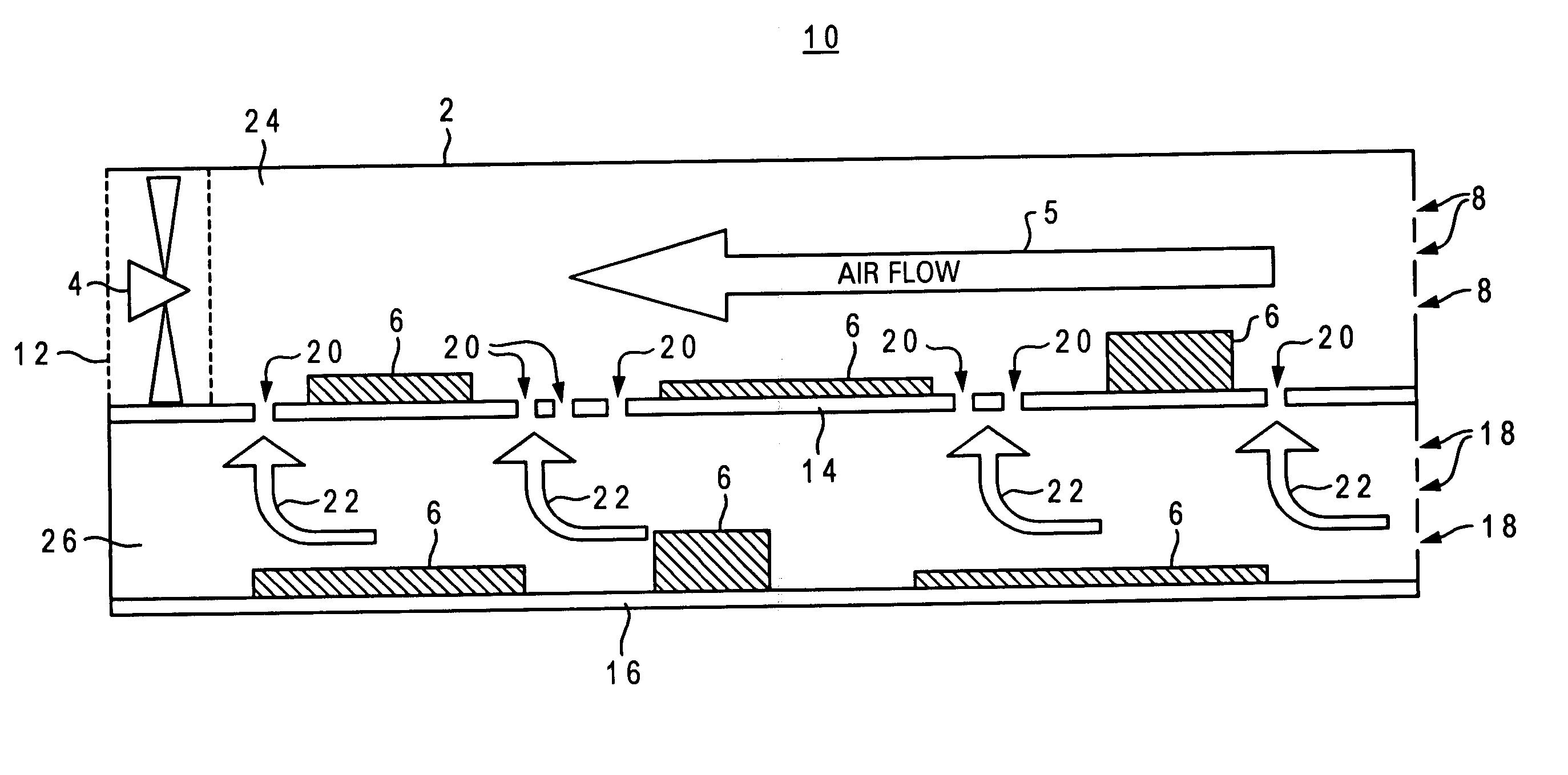
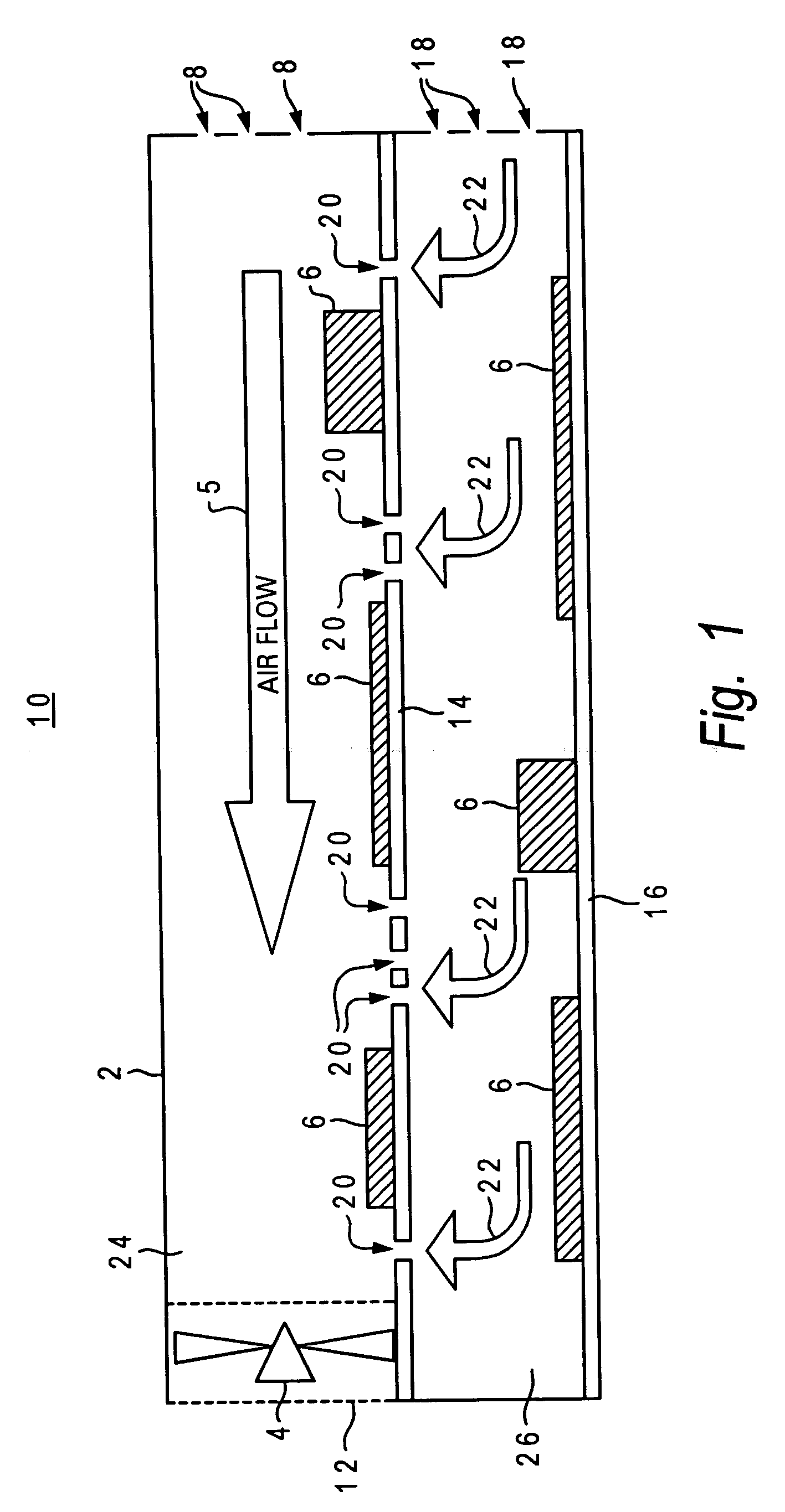
[0014] The present invention is generally directed to an apparatus and method for cooling electronic components that may be housed within an electronics mounting package or chassis. In particular, the present invention is directed to improved housing and circuit board units adapted to provide a mixed convection coolant flow that promotes efficient and evenly distributed cooling across multiple board planes. In a preferred embodiment, the present invention is directed to providing enhanced cooling for vertically stacked printed circuit boards (PCBs).

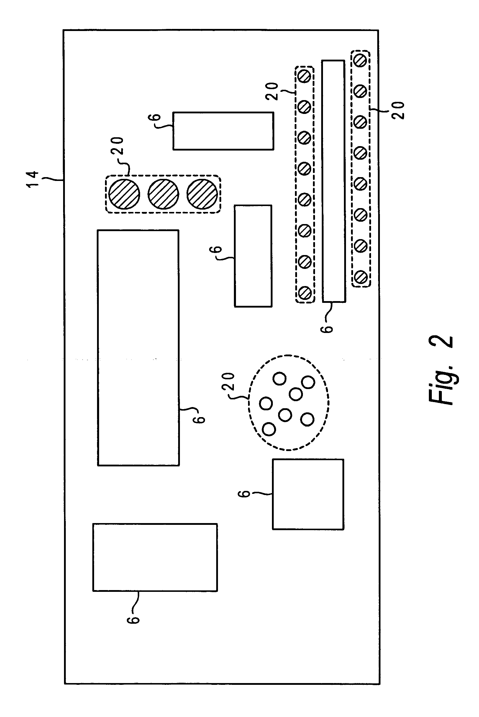
[0015] With reference now to the figures wherein like reference numerals refer to like and corresponding parts throughout, and in particular with reference to FIG. 2, there is illustrated an overhead view of an upper level PCB as may be employed in the PCB apparatus of the present invention. Specifically, an upper level PCB 14 is depicted which, as depicted and explained in further detail below with reference to FIG. 1, may be advantage...


PUM


Abstract

An apparatus, system and method for cooling vertically stacked printed circuit boards (PCBs). In one embodiment, a first PCB is disposed within a substantially enclosed lower chamber inside a PCB containment housing. A second PCB is disposed above the first PCB within the housing to define a substantially enclosed upper chamber above the lower chamber. The second PCB includes one or more airflow apertures defined therethrough and providing vertical air flow coupling between the upper and lower chambers. An airflow actuating device is utilized to generate a primary forced airflow within the upper chamber which is substantially parallel to the surface plane of the second PCB. The primary forced airflow further induces a negative air pressure in the upper chamber such that a mixed convection airflow is established between the upper and lower chambers via the second PCB apertures.

Description

BACKGROUND OF THE INVENTION [0001] 1. Technical Field [0002] The present invention relates generally to cooling printed circuit board components and in particular to an apparatus employing a mixed convection airflow mechanism for cooling vertically stacked printed circuit boards. [0003] 2. Description of the Related Art [0004] With microelectronics technology steadily increasing integrated circuit (IC) chip density and the density in which such circuits are mounted onto system planar printed circuit boards (PCBs), cooling issues are becoming increasingly critical to design of large-scale data processing systems. Electronic systems containing densely packaged components typically utilize fans or blowers for forced-air cooling. [0005] Systems for cooling electronic components mounted within a computer housing may provide circulation of a fluid coolant medium (usually air) by means of a distributed fan system adapted to circulate air throughout the housing. In concert therewith, or in ...

Claims


Application Information

Patent Timeline
IPC IPC(8): H05K7/20
CPCH05K1/0272H05K1/144H05K7/20136H05K2201/09063
Inventor WOLFORD, ROBERT RUSSELLHARDEE, DONNA CASTEELFOSTER, JIMMY GRANT SR.KEENER, DON STEVEN
Owner LENOVO GLOBAL TECH INT LTD
Why Eureka
Try Eureka