

Fuel cell system and control method thereof
- Summary
- Abstract
- Description
- Claims
- Application Information
AI Technical Summary
Benefits of technology
Problems solved by technology
Method used
Image

Examples
first embodiment
[0039] A description will now be given of the features of a fuel cell system according to a first embodiment of the present invention with reference to FIG. 1 to FIG. 5.
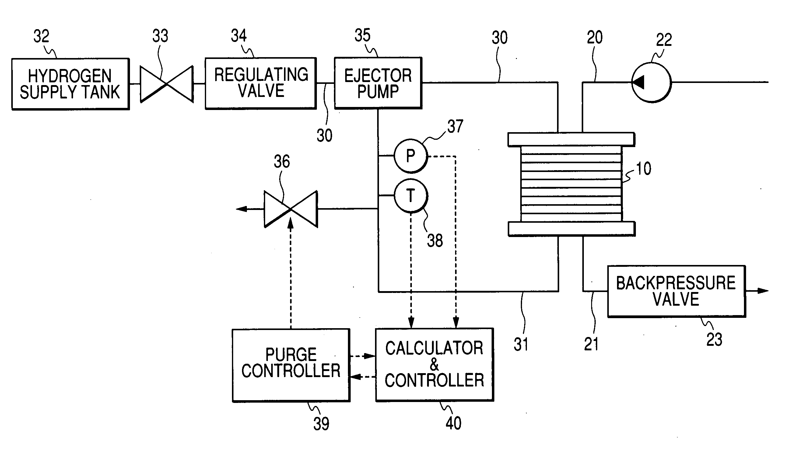
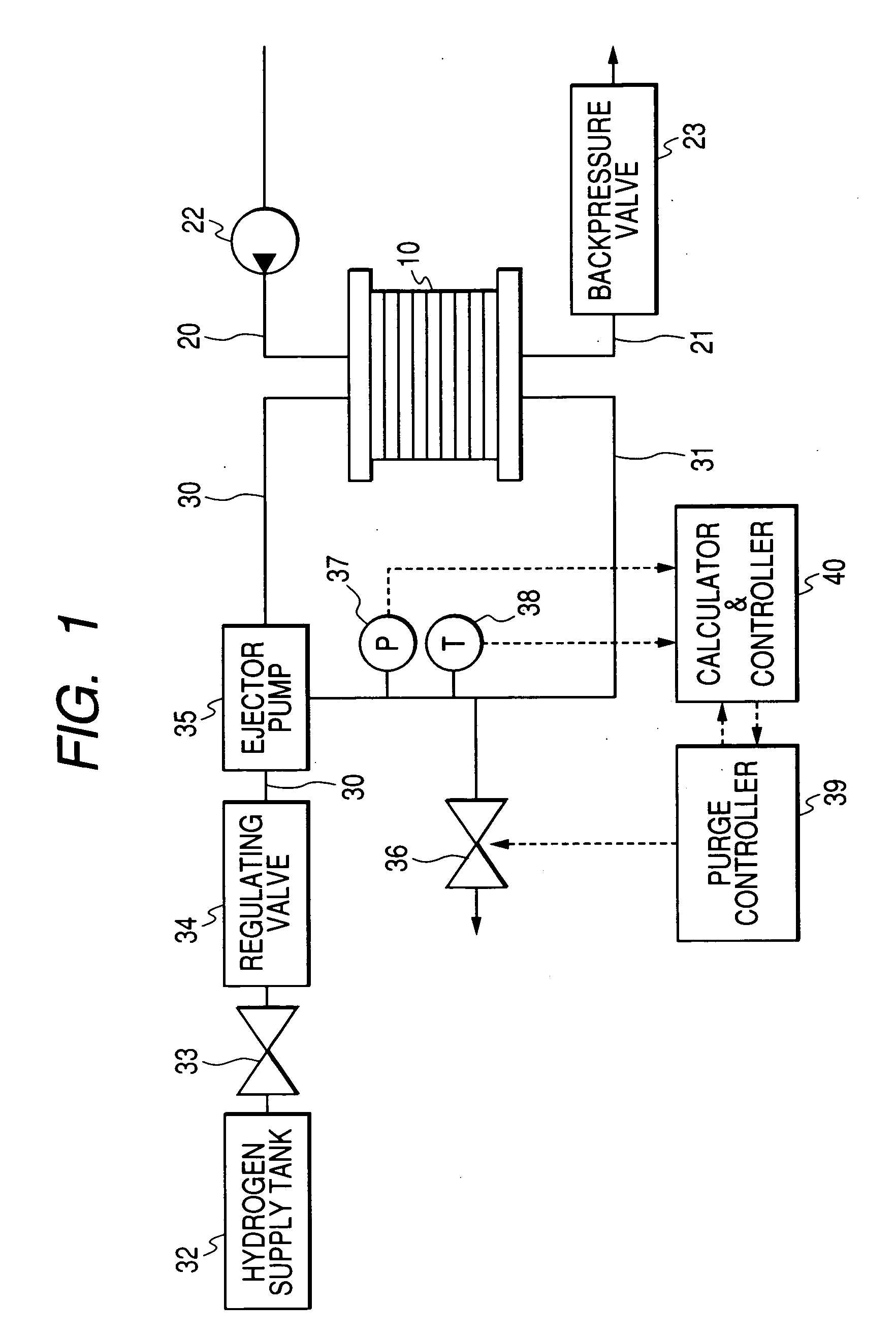
[0040]FIG. 1 shows the entire configuration of the fuel cell system according to the first embodiment of the present invention. In FIG. 1, the fuel cell system has a fuel cell (FC stack) 10 that generates an electrical energy in an electrochemical reaction of a hydrogen and an oxygen. The fuel cell 10 supplies the electrical energy generated to a motor mounted on a vehicle, a secondary battery, and supplementary electrical equipments (omitted from drawings).
[0041] In a case of the first embodiment, the fuel cell 10 is a polymer electrolyte fuel cell (PEFC) in which a plurality of unit cells are laminated and stacked in multilayered structure. Each unit cell has a configuration in which an electrolyte membrane is sandwiched between a pair of electrodes. Each cell generates an electrical energy by an electrochemical ...
second embodiment
[0081] Next, a description will now be given of the feature of the fuel cell system according to the second embodiment of the present invention with reference to FIG. 6 and FIG. 7.
[0082] When compared with the first embodiment, the second embodiment performs a supplemental exhaust through the purging valve 36 in order to obtain the off gas density before the purging. Because the fuel cell system according to the second embodiment is the same in configuration as that of the first embodiment, the explanation thereof is omitted here. The difference operation to the first embodiment will be explained.
[0083] The purging process in the second embodiment will be explained with reference to FIG. 6 and FIG. 7.
[0084]FIG. 6 is a flowchart showing the purging process controlled by the purge controller 39 and the calculator 40 with a control function as the off gas physical property calculator in the fuel cell system of the second embodiment.
[0085]FIG. 7 is a diagram showing a pressure chang...
third embodiment
[0094] Next, a description will be given of the feature of the fuel cell system according to the third embodiment of the present invention with reference to FIG. 8 and FIG. 11.
[0095] When compared with the first and second embodiments, the third embodiment further comprises in configuration a secondary valve with a smaller size in diameter than the purging valve 36.
[0096]FIG. 8 is a schematic diagram showing an entire configuration of the fuel cell system according to the third embodiment of the present invention. As shown in FIG. 8, the off gas circulation path 31 of the third embodiment is further equipped with an off gas circulation pump 41 and a secondary valve 42 of a small diameter.
[0097] The off gas circulation pump 41 circulates the off gas through the off gas circulation path 31 and the hydrogen supply path 30, and the off gas circulation pump 41 is installed in a junction of the off gas circulation paths 31 and the hydrogen supply path 30.
[0098] The secondary valve 42 ...
PUM
 Abstract
Description
Claims
Application Information