Since conventional dental handpieces are constructed to rotate the
dental drill or burr at speeds of up to 500,000 rpm, the bearings are subject to large stress.
Furthermore, asymmetrical thrust generated by drive air impinging tangentially on the turbine places additional stress on the bearings.
However, their service life is still not satisfactory.
It is easily apparent that operating the air bearings and the turbine with the same drive air causes a major
disadvantage.
At
shut down of the drive air, the turbine still rotates while the air pressure is no longer sufficient to fully support the spindle in the bearing sleeves.
This can result in serious damage to the bearing, which in turn limits the service life of the turbine drive unit.
Moreover, although the cylindrical air cushions may properly support the spindle in radial direction, very little support in axial direction is provided.
Although annular air cushions are provided around the thrust washers, the overall surface of these air cushions appears to be quite small considering the potentially large
axial thrust force applied to the spindle upon contact of the burr with a tooth.
The tangential air supply generates asymmetrical thrust and causes asymmetrical loading of the bearings, which increases stress and wear.
Furthermore, the torque generation of the turbine is low due to the only localized drive air supply.
Moreover, parasitic
airflow (drag) is high when the drive air is supplied tangentially at the circumference of the turbine.
Only low
torque transmission is possible between the chuck and the burr in such constructions, higher torque leading to slippage of the burr.
However, the use of this arrangement in an air turbine handpiece is not disclosed.
In fact, the disclosed arrangement could not be used to hold a dental burr, since the engagement between the pin and the chuck is designed for a non-rotating tool and does not easily lend itself to being used with a rotating tool.
It is a
disadvantage of this prior art arrangement that the burr must be rotated in the chuck until the lock and key structures fit together.
Locating the
interlocking mechanism deep in the drive head of the handpiece makes it impossible for the user to visually pre-align the lock and key structure prior to
insertion of the burr.
However, since the turbine is rotating at high speed, it takes some time to gradually slow down and come to a stop.
This is undesirable, since for safety reasons, the dentist must wait until the turbine has fully stopped before removing the handpiece from a patient's mouth.
Furthermore, during this so called rundown period, the continued rotation of the turbine generates a vacuum in the turbine chamber which may lead to contaminants being sucked into the chamber.
However, the valve arrangements of these two patents shut off only the exhaust air conduit, not the drive air and
chip air / water conduits.
Thus, a vacuum may still be generated and
contamination may still occur.
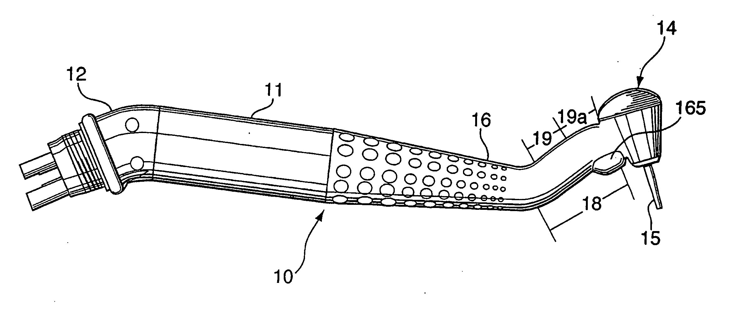
However, the tooth clearance achievable with such a construction is limited by the length of the burr.
Furthermore, the
treatment field is usually partially obstructed during use by the drive head and the neck.
However, this connection normally extends straight in extension of the handpiece, which places a fairly high twisting strain on the
wrist of the user, since the straight swivel connection combined with the inherent rigidity of the
umbilical cord acts as a sort of lever which exaggerates the actual downward force created by the weight of the cord.
This problem has plagued dentists for years with no solution for dental handpieces being available.
However, all of these connectors provide only a straight connection between the umbilical cord and the handpiece.

