Roll embossing of discrete features

a discrete feature and embossing technology, applied in the field of rolling embossing, can solve the problems of plastic deformation throughout the sheet, wrinkling or buckling, and problems in handling and quality

Active Publication Date: 2006-06-15
NOVELIS INC
View PDF23 Cites 29 Cited by
  • Summary
  • Abstract
  • Description
  • Claims
  • Application Information

AI Technical Summary

Benefits of technology

[0015] In another aspect of the invention, there is provided a cold rolling apparatus for impressing a pattern on a surface of a sheet article made of a predetermined metal. The apparatus comprises a pair of rolls each having an outer surface that has a cylindrical part, said rolls being disposed with a gap present between said cylindrical parts of said rolls. One of the rolls of said pair has a localized surface region that is displaced relative to the cylindrical part of said roll such that, when said localized region is brought into proximity with the other roll of said pair, a spacing exists therebetween that is narrower than said gap. In addition, one of said rolls of said pair has a localized patterning feature to be impressed on a surface of said sheet article, said localized patterning feature being aligned with said localized surface region, at least when engaging said sheet article, for impressing said pattern into a surface of said sheet article. The gap is of a width effective to cause said cylindrical parts of said rolls to engage opposite surfaces of said sheet article while imparting compression less than a bulk elastic yield strength of said metal.

Problems solved by technology

These modifications can affect the flatness of the sheet, resulting in wrinkling or buckling with consequent problems in handling and quality.
Traditional patterning methods have used large uniform loads across the surface of the sheet metal, resulting in plastic deformation throughout the sheet as the pattern or logo is applied.
Even very small reductions in metal thickness can cause a loss of flatness in the rolled product.
Hence, conventional roll texturing of sheet surfaces is usually confined to rolling operations incorporating sophisticated methods of flatness control for the strip product.
A further problem in accommodating metal reduction as part of a rolling process to convert surface topography is pattern distortion.
This elongation inevitably distorts any patterning features transferred to the strip from an embossing roll.
Heat is required since, in applying a typical diffraction grating or hologram at low temperature to a metal surface, the following dilemma is faced: a pressure sufficient to reproduce all of the detail can cause distortion of the metal substrate; whereas lower pressure, below the yield strength, can result in clarity and intensity of the pattern being lost.
A number of patent documents, such as Japanese Patent Publications JP 5104102 and JP 9085306, both of which are herein incorporated by reference, disclose forming roll surfaces with projecting and recessed protrusions to roughen sheet metal surfaces, however there is no teaching of achieving distinctive logos on the imprinted sheets.
Still further documents, such as U.S. Pat. No. 5,552,235, herein incorporated by reference, teach embossing methods in which one of the rolls is textured and the other is flat, but again, there is no teaching of creating clear and distinguishable logos, or of preventing changes in the sheet thickness.

Method used


Image

  • Roll embossing of discrete features
  • Roll embossing of discrete features
  • Roll embossing of discrete features

Examples


first embodiment

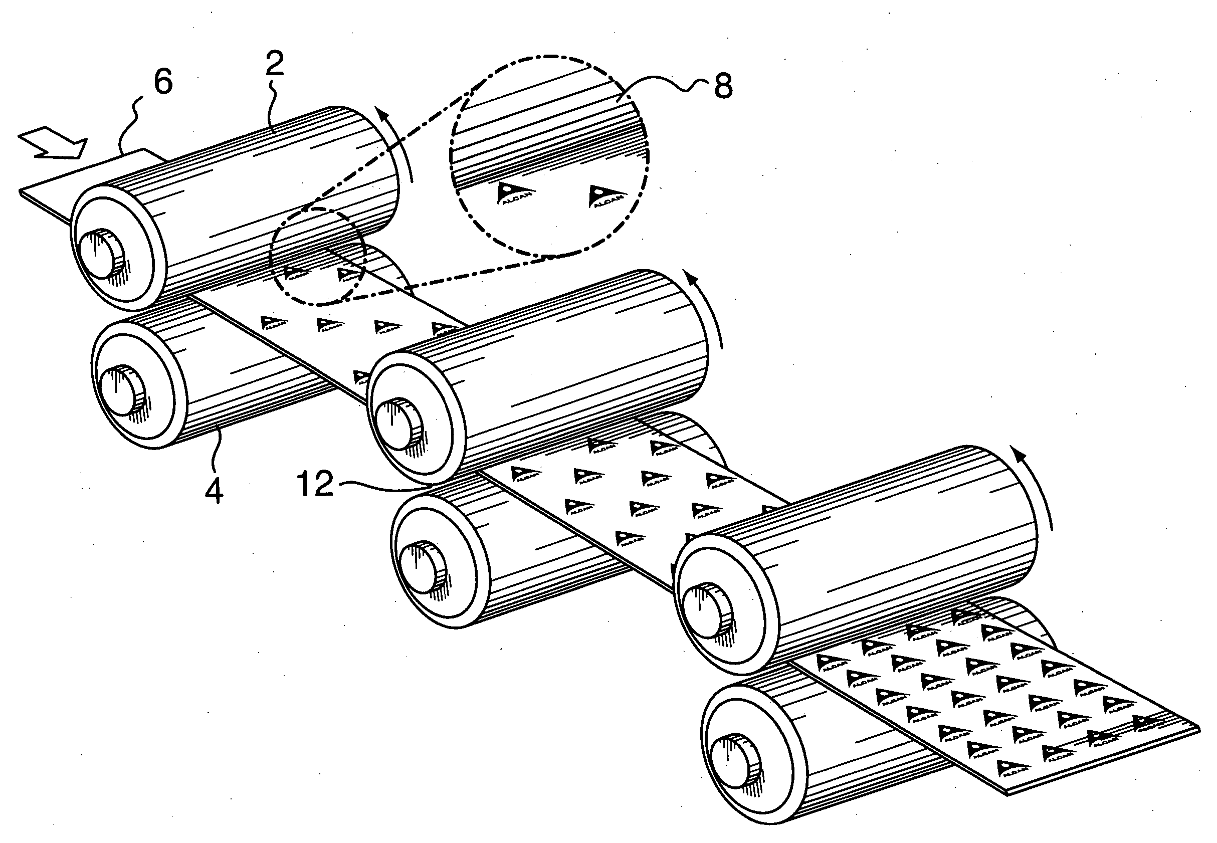
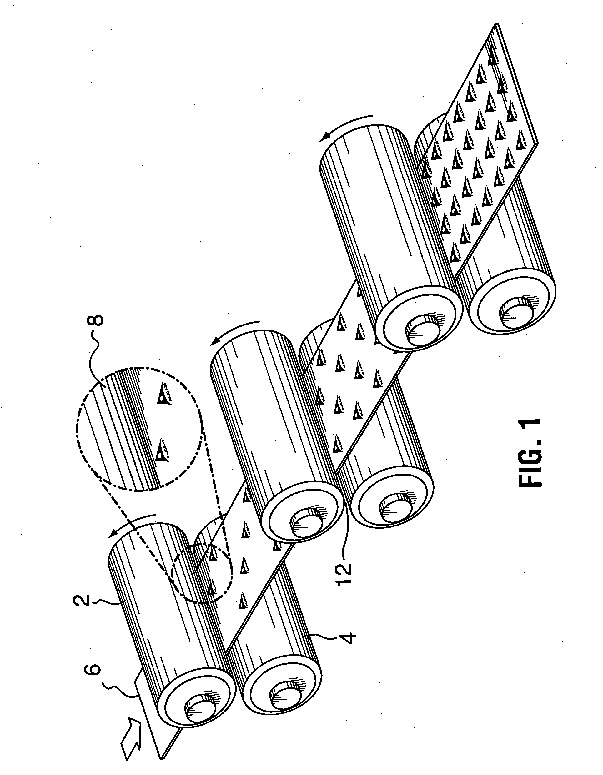
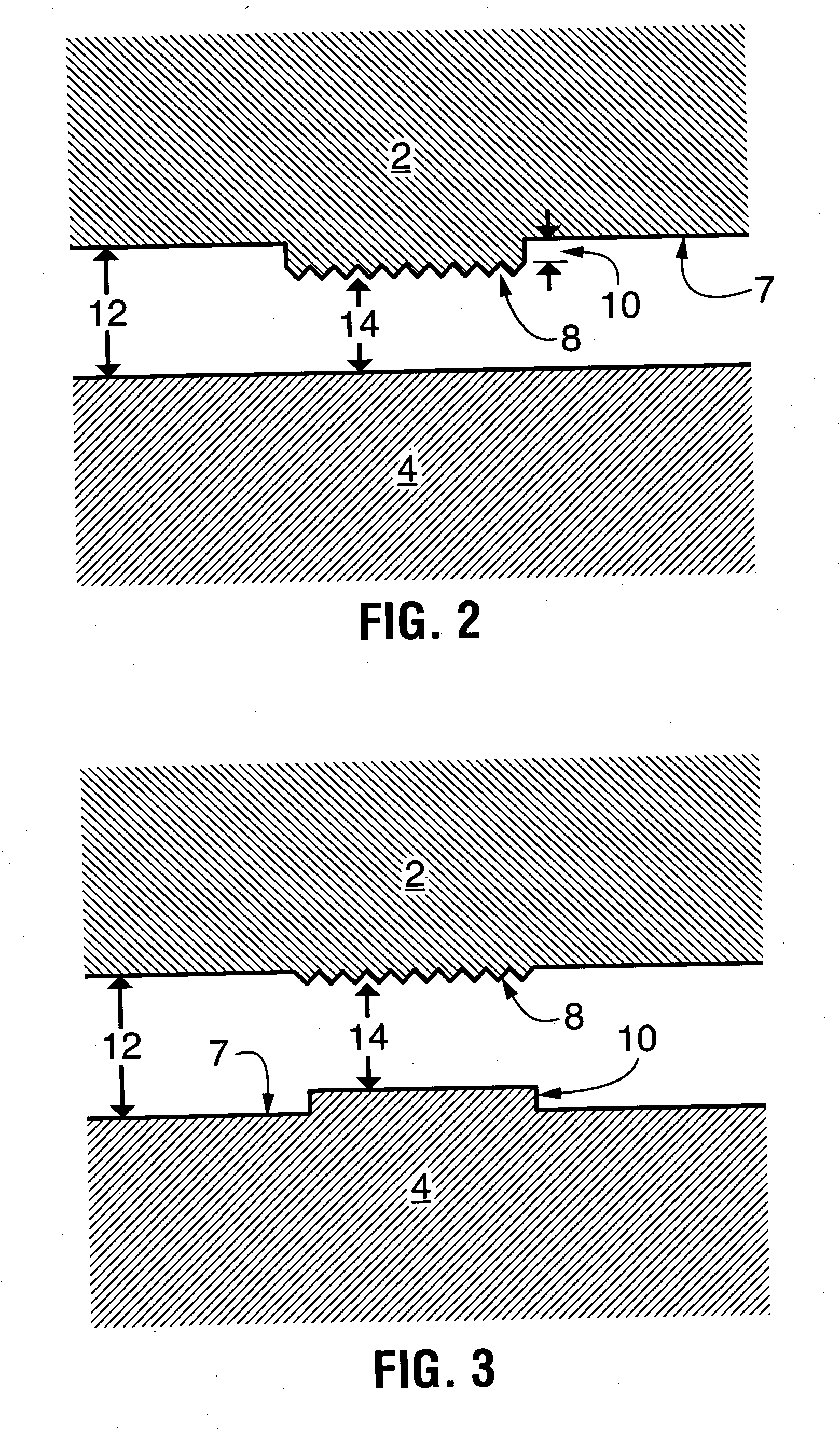
[0028] the present invention is shown in FIG. 2. In this embodiment, a surface of the work roll 2 is selectively back polished in regions 7 between localized patterning features 8 of interest (only one patterning feature 8 is shown in FIG. 2, but several such features could be incorporated on the surface of a single work roll). In this way, the patterning features 8 are left displaced from the remaining cylindrical part of the work roll 2, creating a localized surface region in the form of a plateau feature 10. Material from the surface of the work roll 2 can alternatively be removed by any other well know means such as, for example abrasion, grinding, etching or plasma or spark erosion of the roll surface in between the features of interest.

[0029] As the plateau feature 10 enters the roll-bite, its height relative to the remaining surface of the work roll 2 reduces the roll-gap 12 between the work roll 2 and the counter roll 4. The space 14 created by the reduced roll-gap 12 has th...

third embodiment

[0035] the present invention is shown in FIG. 4, which produces improved sheet article strip having conventional macroscopic embossed features imprinted thereon, but also having a fine scale microscopic pattern imprinted on the macroscopic feature. As seen in FIG. 4, one of the pair of rolls has a projection 16 projecting from its surface and the other of the pair of rolls has a recess 18 extending into its surface. The projection 16 and recess 18 are macroscopic in area and depth. The projection 16 and the recess 18 are shaped and dimensioned so that said projection 16 extends across the roll gap 12 into the recess 18 when the pair of rolls are rotated to bring the projection 16 and recess 18 into alignment. When aligned, the projection 16 and the recess 18 have confronting ends 20. Such rolls are well known in the art and are conventionally used to create macroscopic embossing features on rolled strip metal.

[0036] In this embodiment of the present invention a patterning feature 8 ...

fourth embodiment

[0037] In a fourth embodiment as shown in FIG. 5, similar or different patterning features 8 can be applied to the work roll 2 and the counter roll 4, whereby one or both of the rolls have plateau features 10, to align with each of the patterning features 8, thereby allowing for similar or different patterns to be applied to both surfaces of the sheet article 6.

[0038] In all of the embodiments described above, the thickness and mechanical properties of the sheet article substrate, as well as the nature of pattern to be imprinted will determine how much narrower the space 14 should be than the roll gap 12. As well, the concentration of localized patterns on the roll surface (percentage of the area of the sheet article to be imprinted) will depend upon such factors as the gauge and temper of the metal to be imprinted, the original topography of the sheet metal and the nature of pattern to be imprinted.

[0039] In all of the embodiments described above, the roll gap 12, corresponding to...


PUM

PropertyMeasurementUnit
diameteraaaaaaaaaa
pressureaaaaaaaaaa
elastic yield strengthaaaaaaaaaa

Abstract

A cold rolling process for impressing a pattern on a surface of a sheet metal article involves passing the sheet article through a pair of rolls and engaging a patterning feature with isolated areas of a surface of the sheet article, at a localized pressure to plastically deform at least the surface of the sheet article. A rolling pressure is maintained on other areas of the sheet article that is less than the bulk elastic yield strength of the metal. A cold rolling apparatus is also described having a pair of rolls, each with partially cylindrical outer surfaces. The rolls have a gap between the cylindrical parts. One of the rolls has a localized surface region that is displaced relative to the surface of the roll. When the localized region is brought near the other roll, a spacing exists that is narrower than the gap. One of the rolls has a localized patterning feature that aligns with the localized surface region to impress a pattern into the sheet article. The gap allows the rolls to engage opposite surfaces of the sheet article while imparting compression less than a bulk elastic yield strength of the metal.

Description

CROSS-REFERENCE TO RELATED APPLICATIONS [0001] This application claims the priority right of Applicant's prior Provisional Application Ser. No. 60 / 633,333 filed Dec. 3, 2004.FIELD OF THE INVENTION [0002] The present invention relates to methods and devices for the application of textured patterns on sheet metal. More particularly, it relates to a roll embossing process and apparatus to modify the surface topography of the sheet in discrete areas. Such localized modification of topography can be used to pattern or brand the surface, or to impart a desired function to the surface. BACKGROUND ART [0003] In producing rolled sheet metal products, it is often desirable to apply to a portion of the product a logo or pattern, to identify a particular brand, distinguish the product from other similar products, or to modify certain properties of the surface. The scale of surface modification need only involve microscopic changes in topography, or depth, relative to the sheet metal thickness. ...

Claims


Application Information

Patent Timeline
Patent Type & Authority Applications(United States)
IPC IPC(8): B44B5/00
CPCB21B1/227B21B27/005B21D13/04B21H8/005B21H8/02B44B5/00B44B5/0009B44B5/0047B44C1/24
Inventor BALL, MELVILLE DOUGLASHUNTER, JOHN ANTHONYSMITH, GARY J.
Owner NOVELIS INC
Why Eureka
Try Eureka