Conductive polymer composite structure

a composite structure and polymer technology, applied in the direction of electrolytic capacitors, transportation and packaging, synthetic resin layered products, etc., can solve the problems of difficult formation of conductive polymers on the conductive substrate, and achieve good deformation properties

Inactive Publication Date: 2006-06-15
EAMEX
View PDF34 Cites 32 Cited by
  • Summary
  • Abstract
  • Description
  • Claims
  • Application Information

AI Technical Summary

Benefits of technology

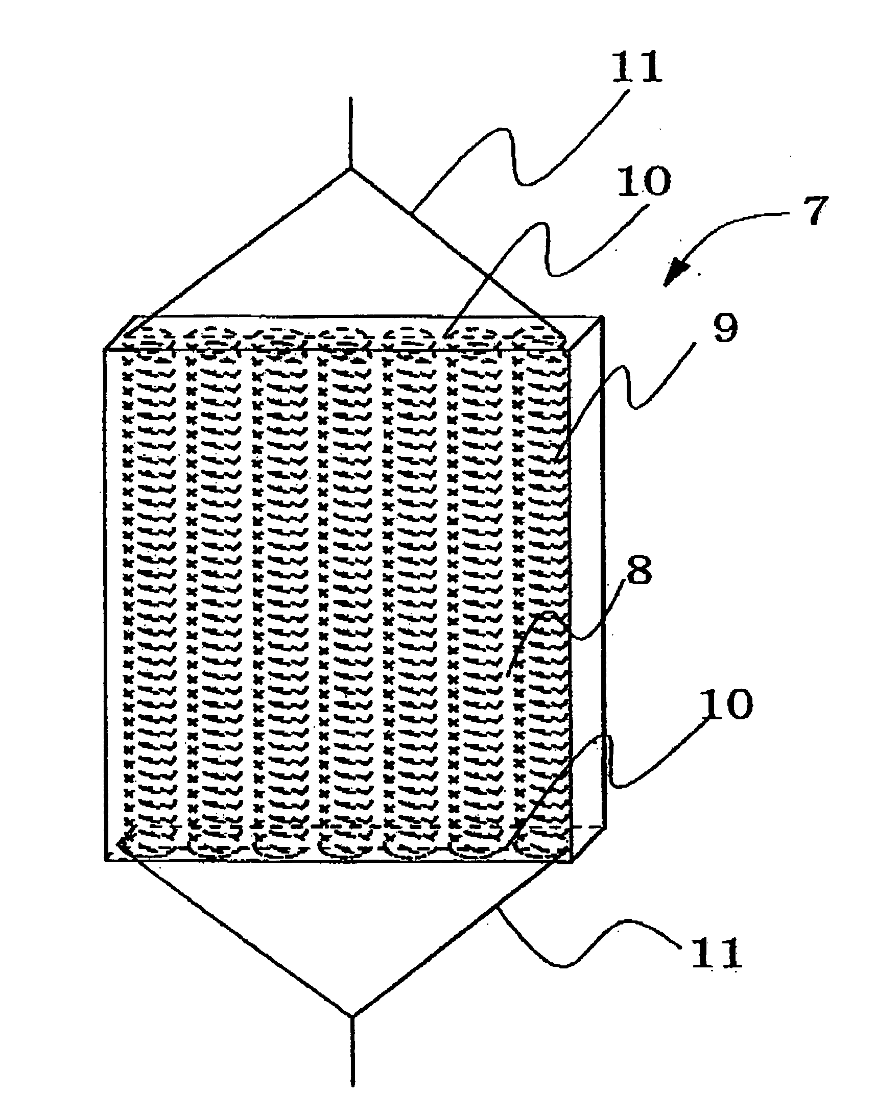
[0012] The present invention relates to conductive polymer composite structures comprising conductive substrates and conductive polymers, wherein said conductive substrates have deformation property and conductivity of said conductive substrates is not less than 1.0×10³ S / cm. By using said conductive polymer composite structures, deformation property is good even when the conductive polymer composite structures are used as larger sized actuator elements. Since said conductive polymer composite structures are provided with structures capable of applying potential to whole elements even when they are used as conductive polymer elements elongated in size in the length direction and in height direction, satisfactory voltage can be applied for driving end portions when used as actuators.
[0013] In addition, since the present invention relates to a process for producing conductive polymer composite structures in which electrode holders which can be immersed in an electrolytic bath are immersed in electrolytic solution and then conductive polymers and conductive substrates are combined by electrochemical polymerization interposing electrolyte between a counter electrode and a working electrode and since the present invention relates to a process for producing conductive polymer composite structures in which said working electrode holders are provided with working electrodes, working electrode terminal portions, and electrode holder portions and in which said working electrodes are attached to said working electrode terminal portions, and said working electrodes include at least coiled conductive substrates. In said production process, since electrochemical polymerization is conducted in a state where counter electrodes are put in the vicinity of working electrodes, a large number of conductive polymer composite structures can easily be obtained for short times at the same time.

Problems solved by technology

When conductive substrates which are said working electrodes are coiled, resistance gets large since metal wires are thin and long, and the larger the conductive substrates get, the less potential transmission becomes, causing the problem of difficulty in forming conductive polymers on the conductive substrates.

Method used

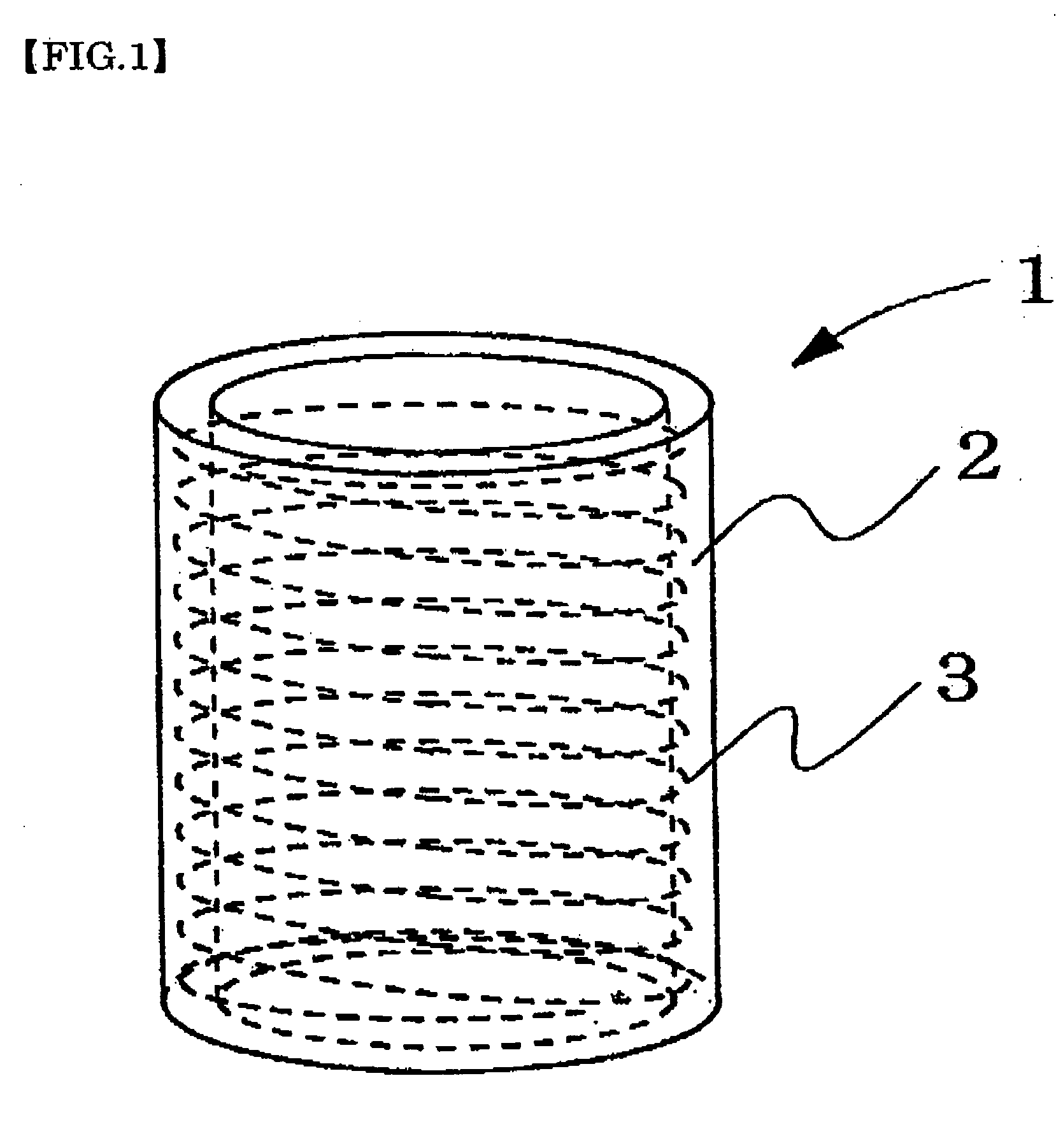
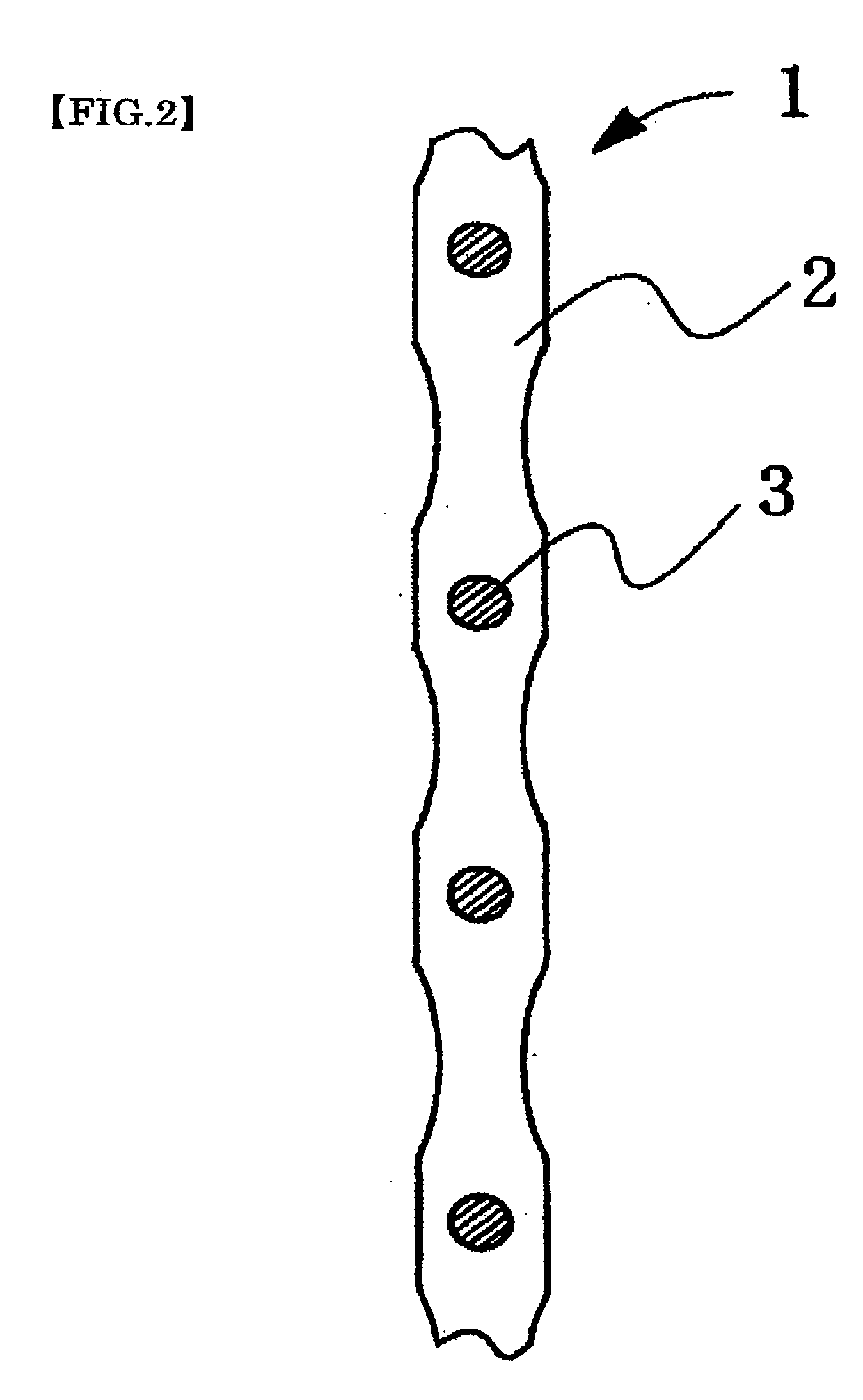

Image

  • Conductive polymer composite structure
  • Conductive polymer composite structure
  • Conductive polymer composite structure

Examples


example 1

[0136] Electrolytic solution was prepared by dissolving pyrrole which is a monomer and a dopant ion salt as shown in Table 1 into medium stated in Table 1 by a publicly known stirring method. This electrolytic solution has monomer concentration of 0.25 mol / l and the dopant salt in Table 1 is 0.5 mol / l. Conductive polymer composite structures of Example 1 having the shapes shown in Table 1 were obtained by using this electrolytic solution and by conducting electrochemical polymerization with constant current methods with the current density of 0.2 mA / cm2 by setting working electrodes and counter electrodes. As said working electrodes, conductive substrates shown in Table 1 (metal mesh, trade name “Au Ami 0.1 mmφ, 100 mesh”, manufactured by Tokuriki Honten Co., Ltd) were used. As said counter electrodes, commercially available Pt electrodes were used. In addition, in the tables, “-” shows that there were no appropriate matters,

example 2

[0137] Conductive polymer composite structures of Example 2 were obtained in the same way as in Example 1, except that conductive substrates of Table 1 (metal mesh, Ni mesh (0.05 mmφ, 200 mesh) manufactured by Rare Metallic Co., Ltd.) were used.

examples 3 to 8

[0138] Conductive polymer composite structures of Examples 3 to 8 were obtained in the same way as in Example 1, except that conductive substrates which were coiled spring members of Tables 1 and 2 were used and that the solvent and dopant salt of Table 1 or 2 were used. In addition, as coiled spring members used in Example 3, spring members formed as a characteristic of Table 1 were used by using “Ni wire, wire diameter 0.10 mmφ” (manufactured by Rare Metallic Co., Ltd.) and as coiled spring members used in Example 4, trade name “SUS / Ni plated coil, outer diameter 0.5 mmφ, wire diameter 40 mmφ, pitch 110 μm” (manufactured by Nippon cable system Inc.) were used. As coiled spring members used in Example 5, “Pt / w coil, outer diameter 0.5 mmφ, wire diameter 40 μmφ, pitch 110 μm” (manufactured by Nippon cable system Inc.) were used. And in Examples 6 and 8, “W coil, outer diameter 0.25 mmφ, wire diameter 0.03 mm, pitch 60 μm” (manufactured by Nippon cable system Inc.) were used. In Exam...


PUM

PropertyMeasurementUnit
conductivityaaaaaaaaaa
widthaaaaaaaaaa
conductivityaaaaaaaaaa

Abstract

In order to obtain actuator elements capable of being displaced such as expansion and contract or bending for practical use even when used as actuator elements with larger size, stacked layers or bundles in which conductive polymer-containing layers or fiber-like tubes are provided with conductive polymer composite structures which include conductive substrates and conductive polymers, said conductive substrates have deformation property, and conductivity of said conductive substrates is not less than 1.0×10³ S / cm are used.

Description

FIELD OF THE INVENTION [0001] The present invention relates to conductive polymer composite structures in which conductive polymers and conductive substrate are composite, process for producing the same, process for producing conductive polymers, bundles and stacked layers of conductive polymer composite structures. BACKGROUND ART [0002] Conductive polymers such as polypyrrole and the like are known to have electrochemomechanical deformation, phenomena of expansion and contraction by electrochemical redox reaction. Recently, this electrochemomechanical deformation of conductive polymers has been attracting public attention, because this is expected to be applied for the use of artificial muscles, robot arms, artificial arms, actuators and the like and applications not only for smaller equipments such as for micro machines and the like, but also for larger machines have been attracting public attention as well. [0003] As a process for producing conductive polymers, a process by elect...

Claims


Application Information

Patent Timeline
Patent Type & Authority Applications(United States)
IPC IPC(8): H01G9/00C25D11/00F16F15/00
CPCF16F15/005Y10T428/32Y10T29/417Y10T428/325Y10T428/31504Y10T428/31551
Inventor ZAMA, TETSUJIHARA, SUSUMUSEWA, SHINGO
Owner EAMEX
Why Eureka
Try Eureka