Voltage-multiplier circuit

a voltage-multiplier and circuit technology, applied in the direction of power conversion systems, instruments, dc-dc conversion, etc., can solve the problems of increasing the cost of materials, and achieve the effect of cost reduction and convenient fixing

Inactive Publication Date: 2006-06-15
NOSICA INT
View PDF7 Cites 6 Cited by
  • Summary
  • Abstract
  • Description
  • Claims
  • Application Information

AI Technical Summary

Benefits of technology

[0006] Accordingly, an object of the present invention is to provide a voltage-multiplier circuit. The voltage-multiplier circuit of the present invention can fabricate a multi-level voltage-pumping blocks, and the voltage-pumping blocks just need to replace diodes and capacitors so that proceed fixing and adjusting the range of the voltage-pumping without using voltage-pumping chip, changing the layout of the printed circuit board or the design of the circuit. Therefore, the present invention is further to achieve the purpose of the cost down and easy for fixing.

Problems solved by technology

The voltage-pumping circuit having the disadvantages below: high energy of EMI caused by the result of high frequency oscillating, however, using the IC with low EMI will increase the cost of the material; the pumping-voltage IC manufactured by different company is not compatible with each other and having the effect of the product deadline and the yield; when the used IC stop manufacturing, the design and the layout of the printed circuit board must be changed.

Method used


Image

  • Voltage-multiplier circuit
  • Voltage-multiplier circuit
  • Voltage-multiplier circuit

Examples


Embodiment Construction

[0026] Now, the preferred embodiments according to the present invention will be described with references to the accompanying drawings.

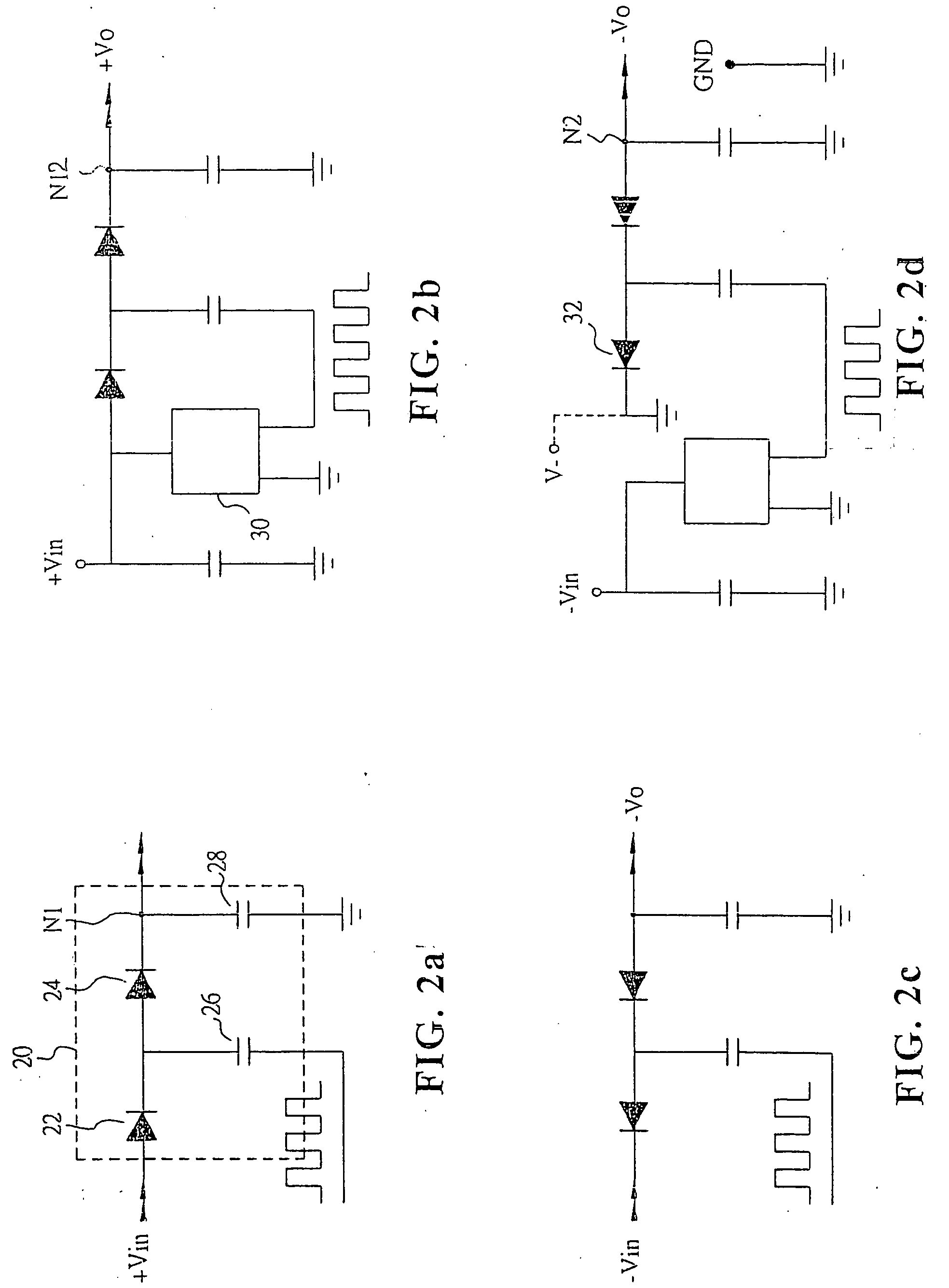
[0027]FIG. 2a is a diagram of the positive voltage-multiplier according to the preferred embodiment of the present invention. Referring to the FIG. 2a, the positive voltage-multiplier circuit includes a voltage-pumping block 20. The voltage-pumping block 20 comprises a first diode 22, a second diode 24, a first coupling capacitor 26 and a second coupling capacitor 28, wherein a side of the first diode 22 for receiving a positive voltage Vin, and the other side of the first diode 22 is connected to a side of the first coupling capacitor 26 and the second diode 24. The other side of the first coupling capacitor 26 receives a functional signal. The other side of the second diode 24 is connected to a side of the second coupling capacitor 28 and output a voltage at node N1. The other side of second coupling capacitor 28 is connected to ground.

[0028]FIG...


PUM


Abstract

The invention provides a voltage-multiplier circuit, and comprises a voltage-pumping block and a functional generator. The voltage-pumping block is composed of a first diode, a second diode, a first couple capacitor, a second couple capacitor to pump an input voltage. The invention can form the multi-level voltage-pumping blocks, and the voltage-pumping block is only needed to replace the diode and the capacitor to repair and increase/decrease the numbers of the diodes and the capacitors to achieve easily adjust the range of the voltage-pumping to achieve the object of decreasing the time and costing saving.

Description

BACKGROUND OF THE INVENTION [0001] 1. Filed of the Invention [0002] This invention relates to a voltage-multiplier circuit and, in particular, relates to a voltage-multiplier circuit by using diodes and capacitors to achieve the effect of the voltage-pumping. [0003] 2. Description of Prior Art [0004] Conventionally, a step-up DC / DC controller IC using diodes, MOSFET, inductor, Schottky Diodes, and filter capacitor so as to achieve the voltage-pumping of the positive or negative voltage. As the conventional circuit of the positive voltage-multiplier circuit shown in FIG. 1, it comprises transistors or MOSFET 10, inductor 11, schottky diode 12, capacitor 13, capacitor 14, capacitor 15, and step-up DC / DC controller IC 16. [0005] The voltage-pumping circuit having the disadvantages below: high energy of EMI caused by the result of high frequency oscillating, however, using the IC with low EMI will increase the cost of the material; the pumping-voltage IC manufactured by different compan...

Claims


Application Information

Patent Timeline
Patent Type & Authority Applications(United States)
IPC IPC(8): G05F1/10H02M3/07
CPCH02M3/073H02M3/07
Inventor WU, KUO CHUANCHEN, TUN JEN
Owner NOSICA INT
Why Eureka
Try Eureka