Method of manufacturing liquid discharging head, and liquid discharging head

Inactive Publication Date: 2006-06-15
CANON KK
View PDF10 Cites 29 Cited by
  • Summary
  • Abstract
  • Description
  • Claims
  • Application Information

AI Technical Summary

Benefits of technology

[0014] According to the above-described invention, a minute projection is formed at a location in the cross section of the ink discharge port which is separate from the surface of the substrate and therefore, the deviation of the flying direction of an ink droplet due to

Problems solved by technology

Now, in the above-described ink jet recording head, the shape of the ink flow path determines the discharge amount, the discharge direction and the discharge speed of an ink droplet, and it greatly affects the quality of prin

Method used


Image

  • Method of manufacturing liquid discharging head, and liquid discharging head
  • Method of manufacturing liquid discharging head, and liquid discharging head
  • Method of manufacturing liquid discharging head, and liquid discharging head

Examples


embodiment 1

[0032] The present invention will hereinafter be described in greater detail with respect to some embodiments thereof.

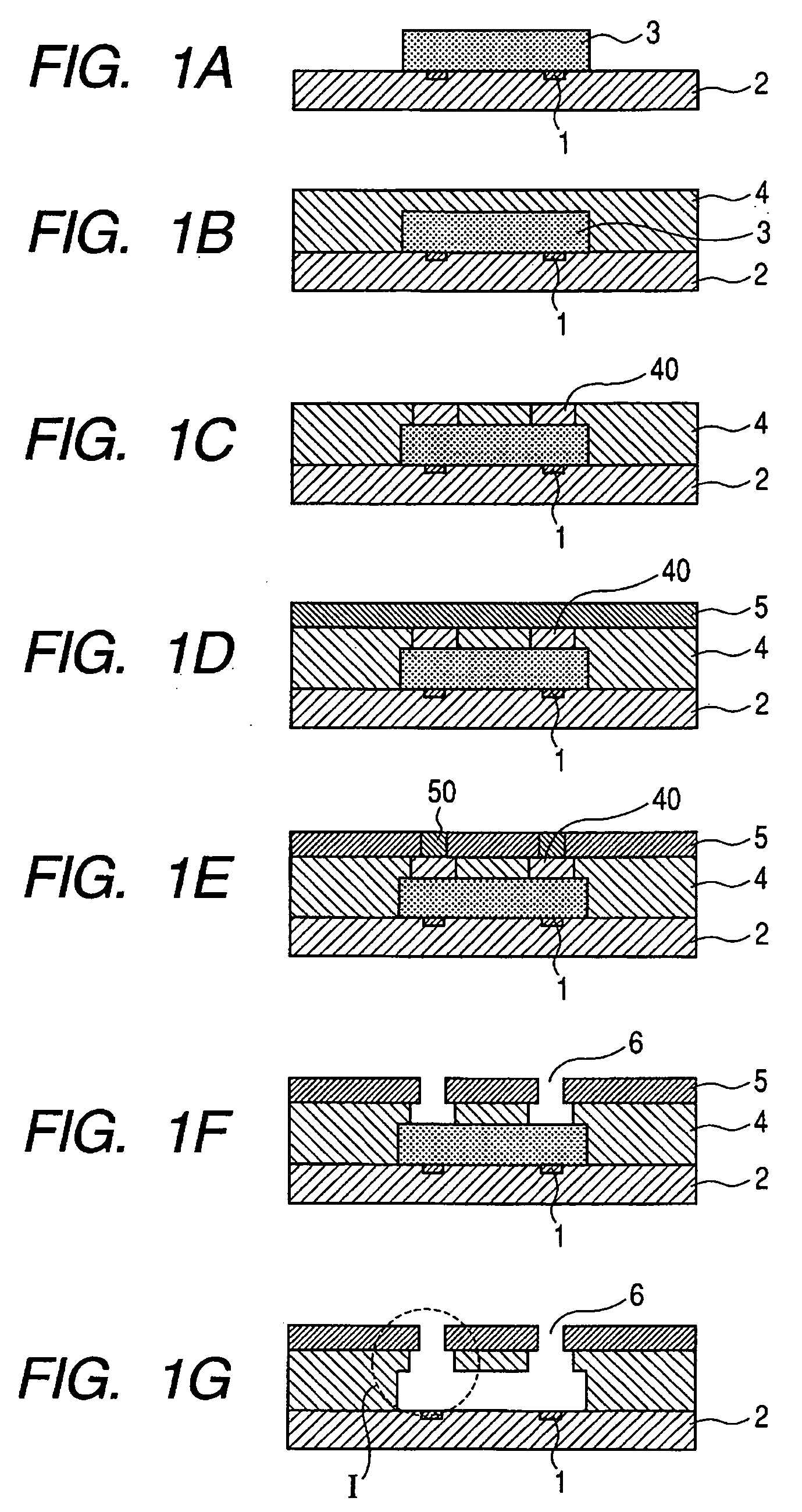
[0033] (1) First, as shown in FIG. 1A, as a positive type resist which is a photodecomposable resin, ODUR-1010 produced by Tokyo Oka Kogyo Co., Ltd. was applied onto the substrate 1 provided with the heat generating resistance member 2 by spin coating, and was prebaked at 120° C. for 3 minutes by a hot plate. It was then exposed at 180 kj / m2 by an aligner UX-3000 produced by Ushio Denki Co., Ltd., whereafter it was developed with methyl isobutyl ketone, and was rinsed with isopropyl alcohol to thereby form the ink flow path pattern 3.

[0034] (2) Next, a negative resist consisting of the following composition was spin-coated as the first nozzle-constituting resin layer 4, and was prebaked at 90° C. for 3 minutes by a hot plate.

EHPE (produced by Diecell Kagaku Kogyo100 parts by weightCo., Ltd.)1,4HFAB (produced by Central Glass Co., Ltd.) 20 parts by weightSP-170 (p...

embodiment 2

[0040] In this embodiment, an ink jet recording head is manufactured by a method similar to that in Embodiment 1 above. However, an aligner FPA-3000EX6 produced by Canon Inc. is used for the exposure of the first nozzle-constituting resin layer 4 effected in item (3) in Embodiment 1 above, and exposure at 400 J / m2 is effected by the use of light of a wavelength of 248 nm. As in the pattern exposure of the ink discharge port, a stepper is used for the exposure at this step, whereby it becomes possible to form a pattern of higher accuracy.

[0041] As the result of printing effected by the use of an ink jet recording head manufactured in this manner, printing of a high quality free of dot-misalignment, irregularity, diminished dot printing, etc. was possible. Consequently, ink discharge free of dot-misalignment, irregularity, diminished dot printing, etc. became possible at a high quality and stably.


PUM

PropertyMeasurementUnit
Areaaaaaaaaaaa

Abstract

The present invention provides an ink jet recording head forming method which can be improved in a discharging characteristic. The method includes at least the step of forming an ink flow path pattern on a substrate by a photodecomposable positive type resist resin, the step of once executing each of the steps of applying, exposing and baking thereon a nozzle-constituting resin layer which is a negative type resist containing an optical cation polymerization starting agent and having an epoxy resin as a chief component with respect to each of an ink flow path pattern and an ink discharge port pattern, the step of collectively developing unexposed portions on the respective nozzle-constituting resin layers, and the step of removing the formed photodecomposable resin. Therefore, a minute projection is formed at a location separate from the substrate surface side of the cross section of the ink discharge port and thus, the deviation of the flying direction of an ink droplet due to the asymmetry of the inner shape of the ink flow path is minimized.

Description

BACKGROUND OF THE INVENTION [0001] 1. Field of the Invention [0002] This invention relates to a method of manufacturing a liquid discharging head for use in an ink jet recording process or the like, and particularly aims at an improvement in the discharging performance of a so-called side shooter type head from which liquid droplets are discharged in a direction perpendicular to a substrate on which an energy generating element is formed. [0003] 2. Related Background Art [0004] As a liquid discharging head for discharging liquid, there is known one which, as disclosed in U.S. Pat. No. 6,155,673, discharges an ink droplet by giving heat energy to a heat generating resistance member to thereby film-boil ink, and communicating a produced bubble with the atmosphere. As a schematic manufacturing method for realizing the above-described ink jet recording head, there is known a method disclosed in U.S. Pat. No. 5,478,606. [0005] This method has the following steps: [0006] (1) The step of f...

Claims


Application Information

Patent Timeline
IPC IPC(8): B41J2/05B21D53/76B23P17/00
CPCB41J2/1603Y10T29/49401B41J2/1639
Inventor SATO, TAMAKIHATTA, MAKIASAI, KAZUHIROSUZUKI, TAKUMI
Owner CANON KK
Why Eureka
Try Eureka