Power supply adaptive feedforward control circuit

a control circuit and power supply technology, applied in the direction of electric variable regulation, process and machine control, instruments, etc., can solve the problems of insufficient control loops for these power supplies, lack of adaptive feedforward scaling regulators that optimize the amplitude of feedforward signals, and inapplicable techniques for resonant power supplies. , to achieve the effect of reducing output ripple, minimizing perturbations, and simple and inexpensiv

Inactive Publication Date: 2006-06-15
ADVANCED ENERGY IND INC
View PDF17 Cites 35 Cited by
  • Summary
  • Abstract
  • Description
  • Claims
  • Application Information

AI Technical Summary

Benefits of technology

[0008] There is provided by this invention a simple and inexpensive adaptive feedforward circuit that minimizes perturbations in an output of a system that delivers power to a plasma process caused by periodic perturbations in a system input. The preferred embodiment reduces output ripple in a power supply that receives power from a rectified three-phase DC bus by sending a combination of the output of a feedback regulator and a feedforward signal that is proportional to the AC component of the DC bus voltage. The feedforward signal is phased to the control input of a power supply to compensate for ripple and transients in the DC bus voltage. The amplitude of the feedforward signal is automatically adjusted by a feedforward scaling regulator to minimize the output ripple of the power supply.

Problems solved by technology

However, these techniques are not applicable to resonant power supplies.
U.S. Pat. No. 6,049,473 utilizes a nonlinear variable-gain amplifier to adjust the small-signal gain of the feedforward signal path according to a pre-determined trajectory, but it lacks an adaptive feedforward scaling regulator that optimizes the amplitude of a feedforward signal based on measurements of the output of the power supply.
The bandwidth of typical control loops for these power supplies is insufficient to compensate for the rapid changes in the bus voltage that occur near the commutation cusps, and this produces ripple peaks in the output of the power supply that occur with a repetition rate of six times the line frequency.

Method used


Image

  • Power supply adaptive feedforward control circuit
  • Power supply adaptive feedforward control circuit
  • Power supply adaptive feedforward control circuit

Examples


Embodiment Construction

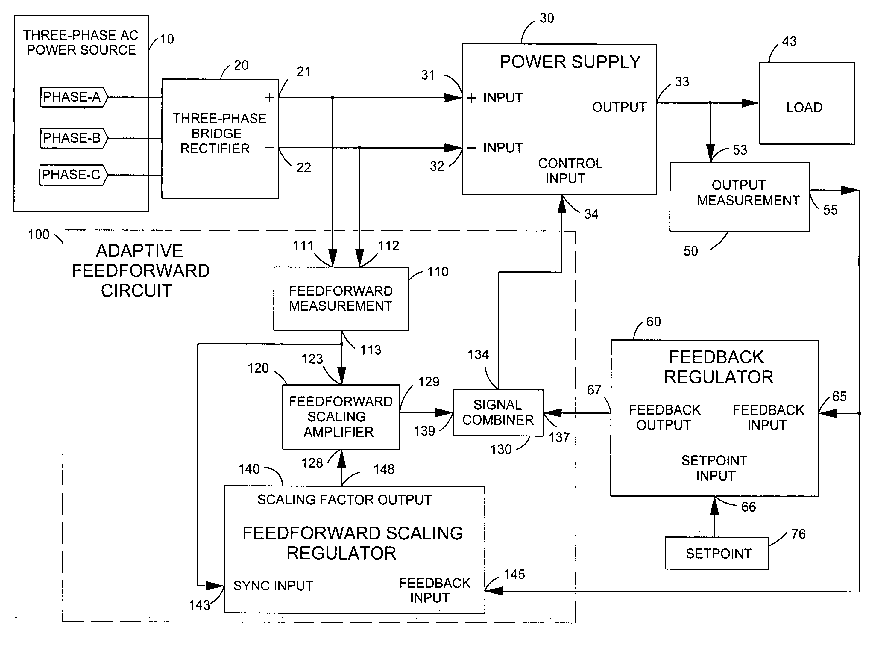
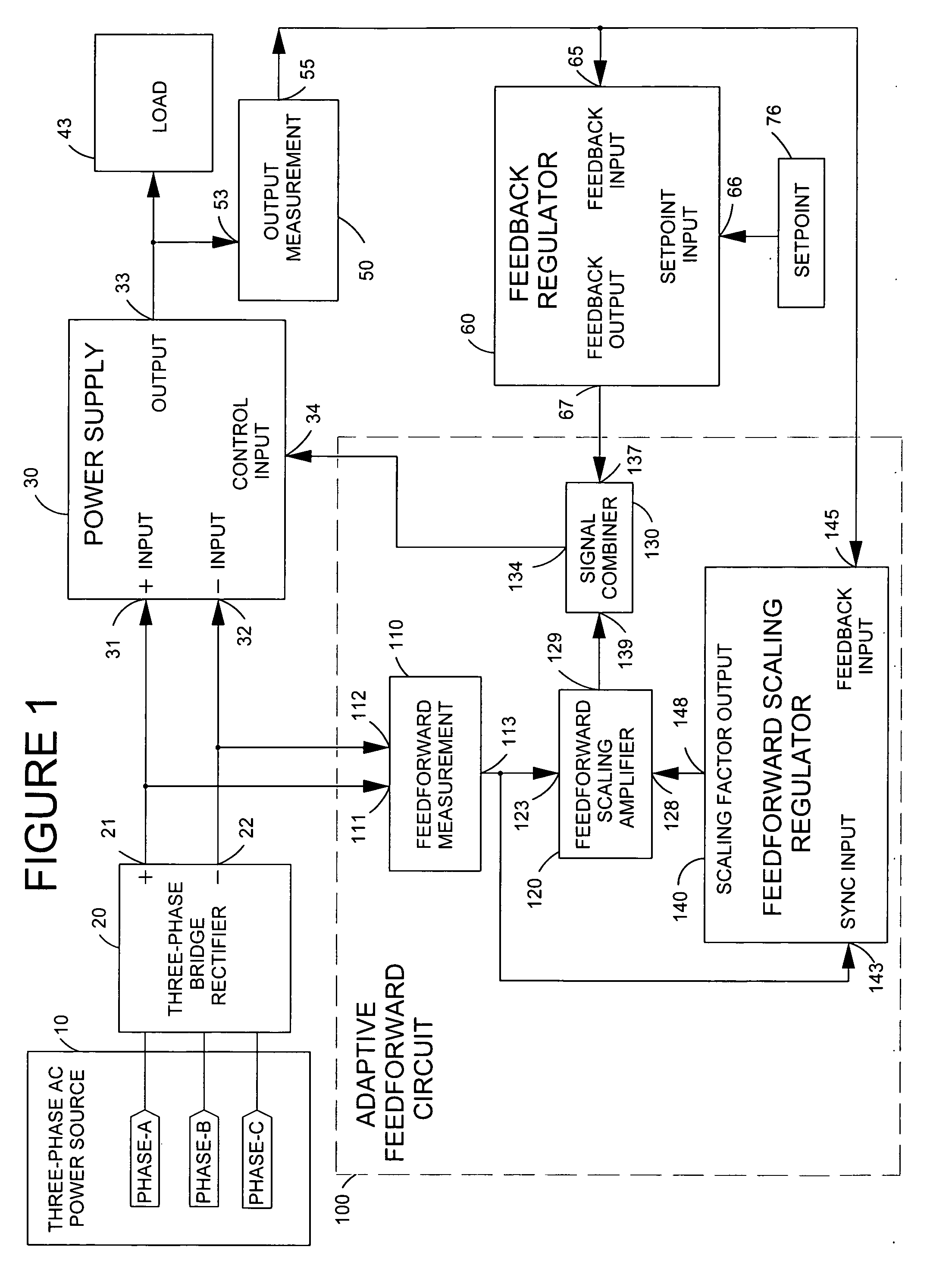
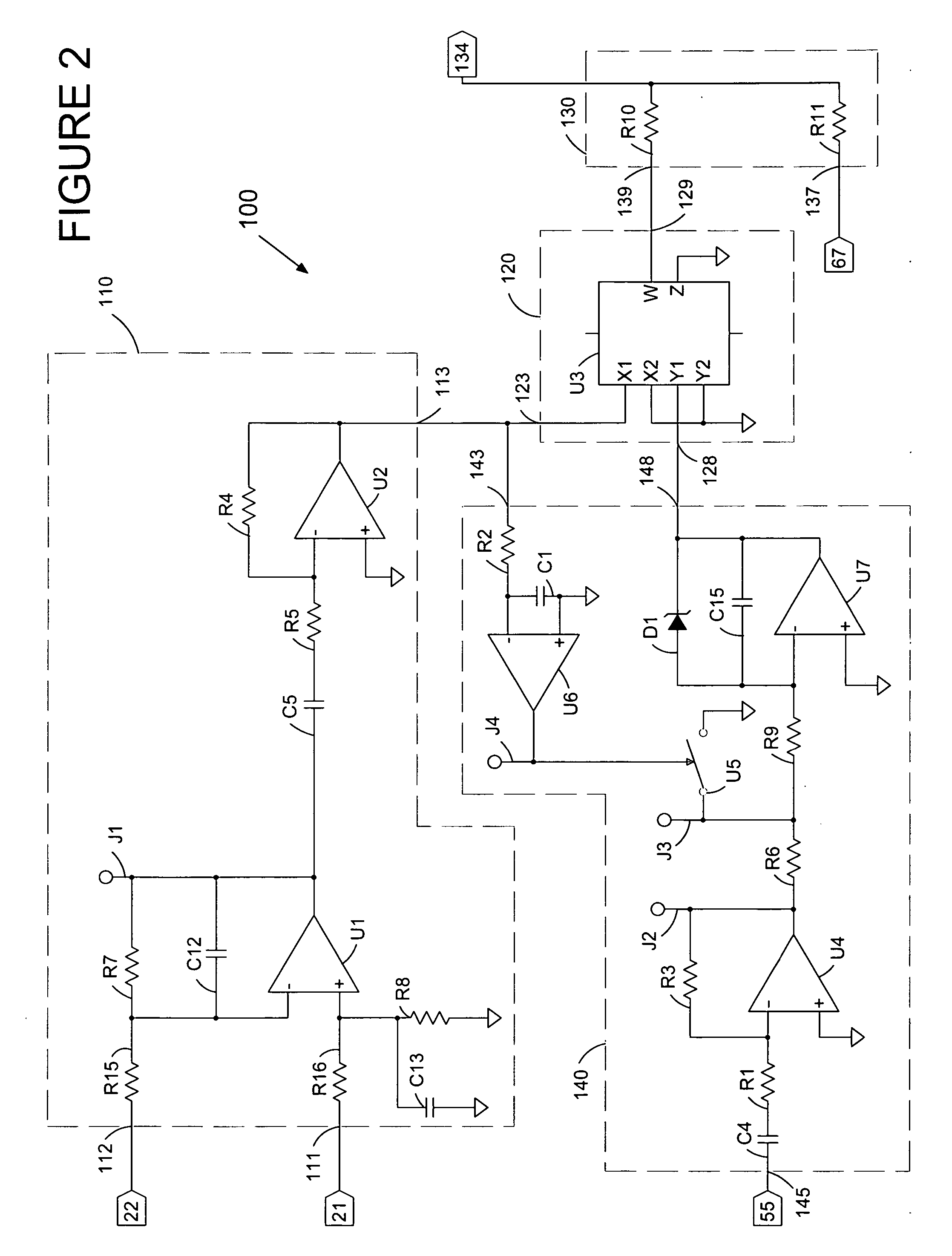
[0012]FIG. 1 shows a block diagram of a power supply system with an adaptive feedforward circuit. A three-phase power source 10 supplies power to a three-phase bridge rectifier 20 that produces a DC bus voltage between a pair of conductors 21 and 22. A power supply 30 has a pair of DC input terminals 31 and 32 that are connected, respectively, to DC bus conductors 21 and 22. The power supply delivers power from an output 33 to a load 43. In general, power supply 30 could provide AC or DC power, depending on the application. An adaptive feedforward circuit 100 provides a scaled feedforward signal 129 that enhances the ability of a feedback regulator 60 to regulate the output of the power supply to achieve a desired voltage, current, or power level specified by a setpoint signal 76. This feedforward signal 129 diminishes perturbations of the output of the power supply due to ripple and transient voltages present across the DC bus conductors.

[0013] In operation, an output measurement ...


PUM


Abstract

There is provided by this invention a system for supply power utilizing a power supply having an adaptive feedforward circuit that uses a gating circuit to periodically apply a feedback signal to an integrator circuit in order to develop an optimal level of a scaled feedforward signal that is used to diminish perturbations of the output of the power supply due to ripple and transient voltages present at the DC bus that supplies power to the power supply. The gating circuit is synchronized to the periodic ripple in the DC bus voltage.

Description

BACKGROUND OF THE INVENTION [0001] 1. Field of the Invention [0002] This invention relates generally to switch mode power supplies, and more particularly, to switch mode power supplies suitable for plasma processing that utilize feedforward control to prevent ripple and transients in the power supply output. [0003] 2. Brief Description of the Prior Art [0004] The ability of a regulated power supply to prevent ripple and transients at the input from being transferred to the output can be improved by taking a signal proportional to the input voltage and combining it with the output from the closed-loop feedback control circuit in a way that counteracts the effect of changes in the input voltage. U.S. Pat. No. 6,359,799 discloses a three-phase power supply that uses feedforward to reduce ripple in the output. The optimal amount of a feedforward signal to be combined with the feedback signal varies with the operating conditions, and fairly elaborate control schemes such as those disclos...

Claims


Application Information

Patent Timeline
Patent Type & Authority Applications(United States)
IPC IPC(8): H02M7/04H02M5/42
CPCH02M3/33507H02M5/458H02M2001/0022H02M1/0022
Inventor HESTERMAN, BRYCE L.
Owner ADVANCED ENERGY IND INC
Why Eureka
Try Eureka