Observation apparatus

a technology of observation apparatus and petri dish, which is applied in the field of observation apparatus, can solve the problems of difficult positioning of petri dish within the range of approximately 5 m required for high-magnification observation under a microscope, limited observation area, and long time-consuming experiments using such cultured cells, etc., and achieve good positional reproducibility

Inactive Publication Date: 2006-06-15
OLYMPUS CORP
View PDF7 Cites 24 Cited by
  • Summary
  • Abstract
  • Description
  • Claims
  • Application Information

AI Technical Summary

Benefits of technology

[0014] According to the present invention, the observation apparatus is provided, which allows for an observation of a specific cell even immediately before and after the culture medium exchanges with a good positional reproducibility.

Problems solved by technology

Otherwise, the observable area may be limited or the container may fall onto the microscope.
Some experiments using such cultured cells last a long period of time, in particular, experiments on cell lineage, in which changes in specific cells are traced, is carried out over a long period of time.
H11-202213, though the petri dish can be held with the use of the shiftable petri dish holder, it is difficult to position the petri dish within a range of approximately 5 μm that is required for a high-magnification observation under a microscope.
Even if the petri dish is positioned within a range of approximately 5 μm with the use of the petri dish holder, it is impossible to position a cell located out of a center within a range of about 5 μm, because the round petri dish cannot controlled in the rotation direction.
Thus, during the long-term observation requiring the exchange of the culture medium, the specific cell practically cannot be observed immediately before and after the exchange of the culture medium.

Method used


Image

  • Observation apparatus
  • Observation apparatus
  • Observation apparatus

Examples


first embodiment

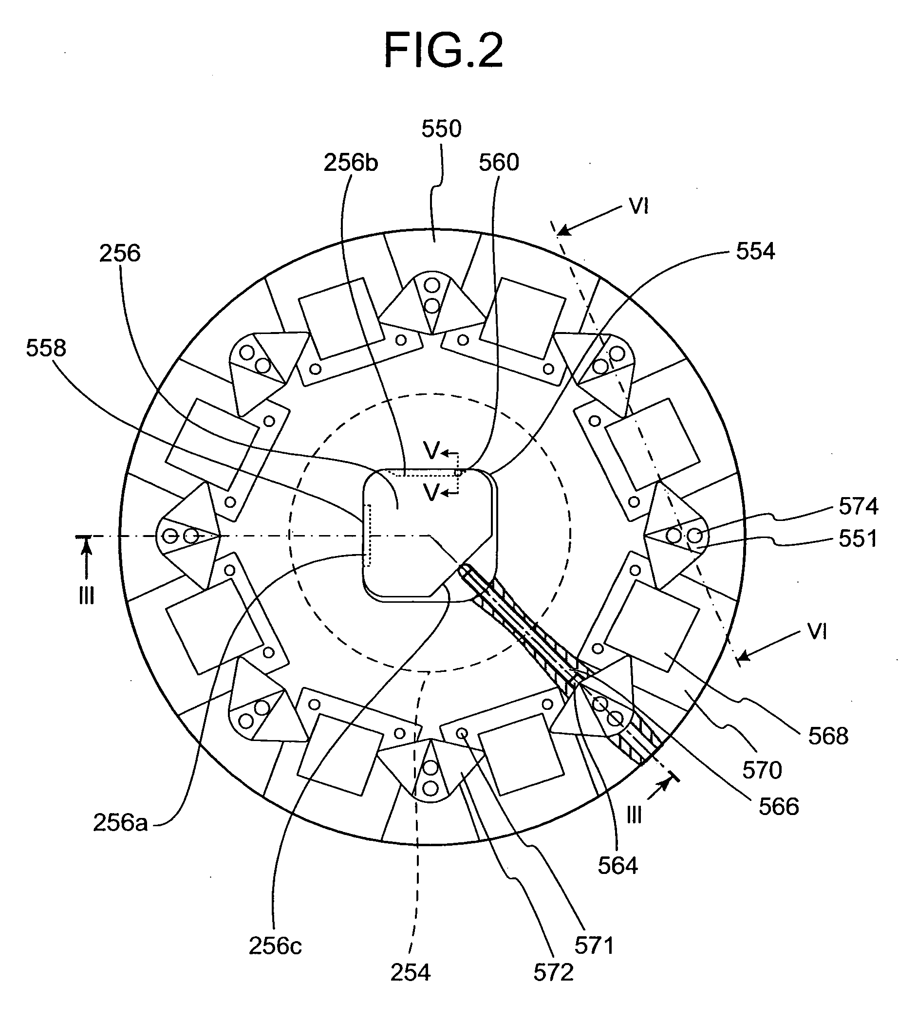
[0076] In the first embodiment, the diameter of the container 512 is 35 mm, and eight samples 510 are arranged on the sample tray 550 along the circumference having a diameter of 160 mm. Since the switching process of the samples 510 is carried out by the rotation of the sample tray 550, no translational shift of the sample tray 550 is required to switch the samples 510. Although the sample tray 550 is translation-shifted so as to adjust the observation position, the amount thereof is limited to approximately 10 mm. Therefore, there is only a little space that allows the sample tray 550 to shift.

[0077] The following description will discuss a comparative example in which nine samples 510 are arranged in a lattice format with longitudinal and lateral positions of 3×3, and switched by using X and Y stages. In this case, translational shifts of the X and Y stages of 80 mm or more are required for the respective X and Y directions. In contrast, in the first embodiment, the sample tray 5...

third embodiment

[0091] A third embodiment is directed to an observation apparatus used for observing a cultured cell. The observation apparatus is formed by an inverted microscope system.

[0092]FIG. 9 schematically shows an observation apparatus in accordance with the third embodiment of the present invention. FIG. 10 shows a stage and a sample tray that are shown in FIG. 9. FIG. 11 is a plan view that shows a container holding mechanism that is installed in the sample tray. FIG. 12 is a sectional view taken along line XII-XII of FIG. 11. In FIG. 12, a sample is also drawn together.

[0093] As shown in FIG. 9, a microscope system 700 includes an objective lens 712, a focusing mechanism 714 used for shifting the objective lens 712 upwards and downwards, and a stage 720 on which a sample tray 750 holding a sample 730 is mounted. The stage 720 can be shifted horizontally. The stage 720 is provided with a depressed portion 722 that has a size larger than the sample tray 750 and an opening 724 that has a ...


PUM

PropertyMeasurementUnit
humidityaaaaaaaaaa
humidityaaaaaaaaaa
temperatureaaaaaaaaaa

Abstract

An observation apparatus includes a sample tray that holds a container housing a cultured cell and a culture medium and covered with a lid; an observation unit that serves for observation of the cultured cell; and a shifting unit that relatively shifts the sample tray and a light axis of the observation unit along a plane that is orthogonal to the light axis of the observation unit, wherein the sample tray includes a container holding unit that holds the container by utilizing an elastic force, and at least one of the lid and one portion of the lid is made detachable, with the container being held in the sample tray by the container holding unit.

Description

CROSS-REFERENCE TO RELATED APPLICATIONS [0001] This application is based upon and claims the benefit of priority from Japanese Patent Application No. 2004-361784, filed on Dec. 14, 2004, the entire contents of which are incorporated herein by reference. BACKGROUND OF THE INVENTION [0002] 1. Field of the Invention [0003] The present invention relates to an observation apparatus used for observing a cultured cell. [0004] 2. Description of the Related Art [0005] In the field of biological research, various experiments have been conducted with the use of cultured cells for the study of dynamic changes in living organisms. The cultured cells are placed in a carbon dioxide incubator that is kept at an inner temperature of 37° C., a carbon dioxide gas concentration of 5%, and a humidity of 100%, together with a liquid referred to as a culture medium made from bovine serum or the like, so that the activities of the cultured cells are maintained. Moreover, observation apparatuses, which allo...

Claims


Application Information

Patent Timeline
Patent Type & Authority Applications(United States)
IPC IPC(8): C12M1/36C12M1/34
CPCC12M23/10C12M23/48C12M23/50C12M41/36
Inventor HASEGAWA, KAZUHIROKAGAYAMA, AKITSUGUENDO, HIDEAKIHIRANO, RYUICHITSUCHIYA, ATSUHIROKOYAMA, KENICHIYAMAGUCHI, KATSUYOSHI
Owner OLYMPUS CORP
Why Eureka
Try Eureka