Acoustical panel coating and process of applying same

a technology of acoustical panels and coatings, applied in the field of ceiling systems, can solve the problems of affecting the appearance of the ceiling, affecting the work environment, and many loudspeaker systems not being integrated visually,

Inactive Publication Date: 2006-06-15
FELEGI JOHN JR +6
View PDF5 Cites 7 Cited by
  • Summary
  • Abstract
  • Description
  • Claims
  • Application Information

AI Technical Summary

Benefits of technology

[0009] The present invention provides a coating composition which, when applied to a substrate, such as an acoustical panel, scrim or facing of a flat panel sound radiator, preserves the acoustical performance characteristics of the substrate and imparts a textured appearance to the substrate making it visually indistinguishable from surrounding panels in a wall or suspended ceiling system. Thus, a monolithic appearance in the wall or ceiling system is achieved.

Problems solved by technology

Additionally, speakerphones, conferencing technologies, and multimedia computers with large sound reflecting screens and voice input tend to increase the noise level of the workplace.
Unfortunately, many loudspeaker systems do not integrate visually into the ceiling system and, as a result, interrupt the desired monolithic appearance of the ceiling.
By way of example, many speaker systems, when installed, protrude below the plane of the acoustical panels, thus interrupting the planar surface of ceiling.
Such a speaker grill, while effective, nevertheless interrupts the monolithic appearance of the ceiling and is considered unsightly by some.
However, existing flat panel sound radiators generally are detectable because the coloring and texture of the facing does not match precisely the surrounding ceiling tiles.
Thus, these flat panel radiators still are considered by some to present an unacceptable appearance.
However, it has proven difficult to formulate a coating and a process for its application which provides the facing material with the proper appearance and texture while continuing to provide the desired acoustic transparency.

Method used


Image

  • Acoustical panel coating and process of applying same
  • Acoustical panel coating and process of applying same
  • Acoustical panel coating and process of applying same

Examples


Embodiment Construction

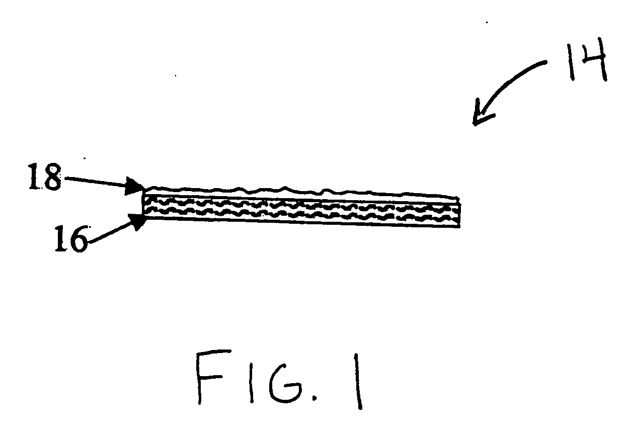
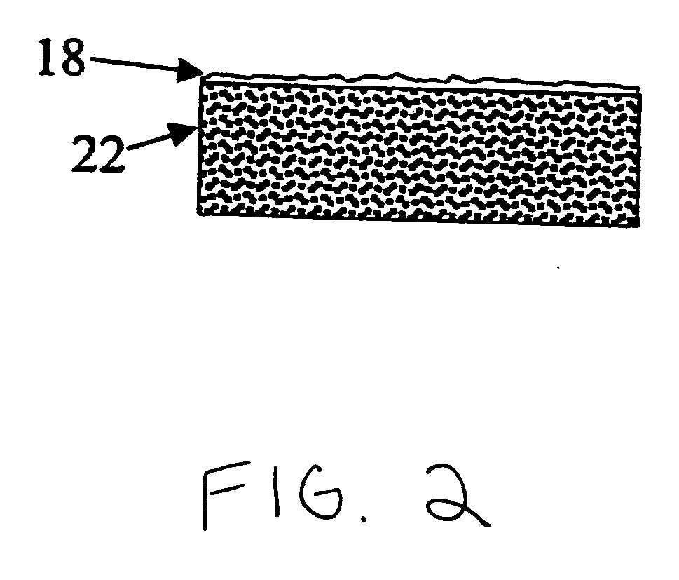
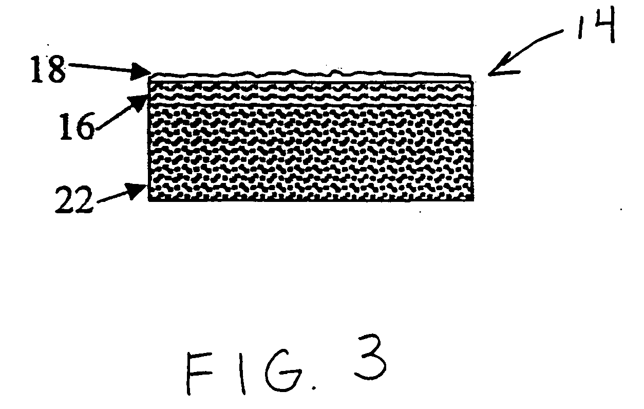
[0019] The present invention is described in further detail below and is shown in the accompanying drawings wherein like numerals refer to like parts throughout the several views.

[0020] The coating composition of the invention includes filler particles, a binder and a liquid carrier. The filler particles are of sufficient size to impart a textured appearance to a substrate, while tending not to completely plug or seal the openings within the substrate. The filler particles have an average particle size in the range from about 100 to about 600 microns and preferably in the range from about 200 to about 450 microns. The filler particles constitute from about 35% to about 90% by weight of the coating composition on a dry solids basis and are preferably formed of calcium carbonate, dolomite, dolomitic limestone or combinations thereof. The calcium carbonate particles have an average particle size of approximately 450 microns and may be screened through a 30 mesh sieve. One example of a...


PUM

PropertyMeasurementUnit
atomization pressureaaaaaaaaaa
particle sizeaaaaaaaaaa

Abstract

A coating composition and process of applying the coating to a substrate are provided herein. The coating composition includes filler particles, binder and a liquid carrier, such as water. The filler particles have an average particle size in the range from about 100 to about 600 microns and preferably in the range from about 200 to about 450 microns. The coating composition comprises from about 15% to about 50% by weight liquid carrier and from about 35% to about 90% by dry solids weight filler particles. The coating composition preserves the acoustic performance characteristics of the substrate to which it is applied, while imparting a textured appearance to the substrate, making the substrate virtually indistinguishable from surrounding panels.

Description

CROSS REFERENCE TO RELATED APPLICATION [0001] This application claims the benefit under 35 U.S.C. § 119(e) of U.S. provisional application Ser. No. 60 / 414,950, filed Sep. 30, 2002.BACKGROUND [0002] The present invention relates generally to ceiling systems having acoustical panels and more particularly to coatings for acoustic scrims of flat panel sound radiators and acoustical panels and a method for applying these coatings. [0003] As the service sector of the economy grows, more and more workers find themselves in offices rather than in manufacturing facilities. The need for flexible, reconfigurable space has resulted in open plan workspaces, large rooms with reduced height, moveable partitions, and suspended ceiling systems. Workstation density also is increasing, with more workers occupying a given physical space. Additionally, speakerphones, conferencing technologies, and multimedia computers with large sound reflecting screens and voice input tend to increase the noise level o...

Claims


Application Information

Patent Timeline
Patent Type & Authority Applications(United States)
IPC IPC(8): B05D3/02C08K3/26B05D1/02B05D5/00B32B7/02C08L23/28C09D5/02C09D7/12C09D201/00
CPCC08L23/286C09D5/028C09D7/1216Y10T428/161Y10T428/164Y10T428/16C09D7/1283C09D7/61C09D7/69Y10T442/174Y10T442/172Y10T442/198
Inventor FELEGI, JOHN JR.PAPE, JAMES D.HARTMAN, JOHN J. JR.HUNTZINGER, SCOTT L.HUNTZINGER, SUZANNE M.LEFEVER, JOANNEHERMESKY, MICHAEL J.
Owner FELEGI JOHN JR
Why Eureka
Try Eureka