Electrical hair remover

Inactive Publication Date: 2006-06-22
SUEN CHI MING
View PDF8 Cites 17 Cited by
  • Summary
  • Abstract
  • Description
  • Claims
  • Application Information

AI Technical Summary

Benefits of technology

[0015] The repeated rotation of the buffing and abrasive surfaces causes flexure of the hair strands near to their roots and below the surface of the skin, while simultaneously reducing the thickness of the hair shaft. The hair shafts become weakened and break off. Visibility is reduced, and the hair root is left intact with this repeated process. The removal of the hair shaft to below the skin surface, by exfoliating the skin, additionally results in a smoother skin surface.
[0016] The buff

Problems solved by technology

The hair shafts become

Method used


Image

  • Electrical hair remover
  • Electrical hair remover
  • Electrical hair remover

Examples


Example

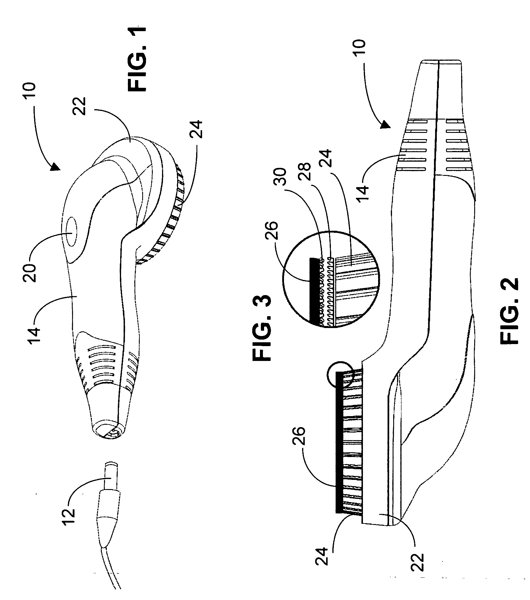
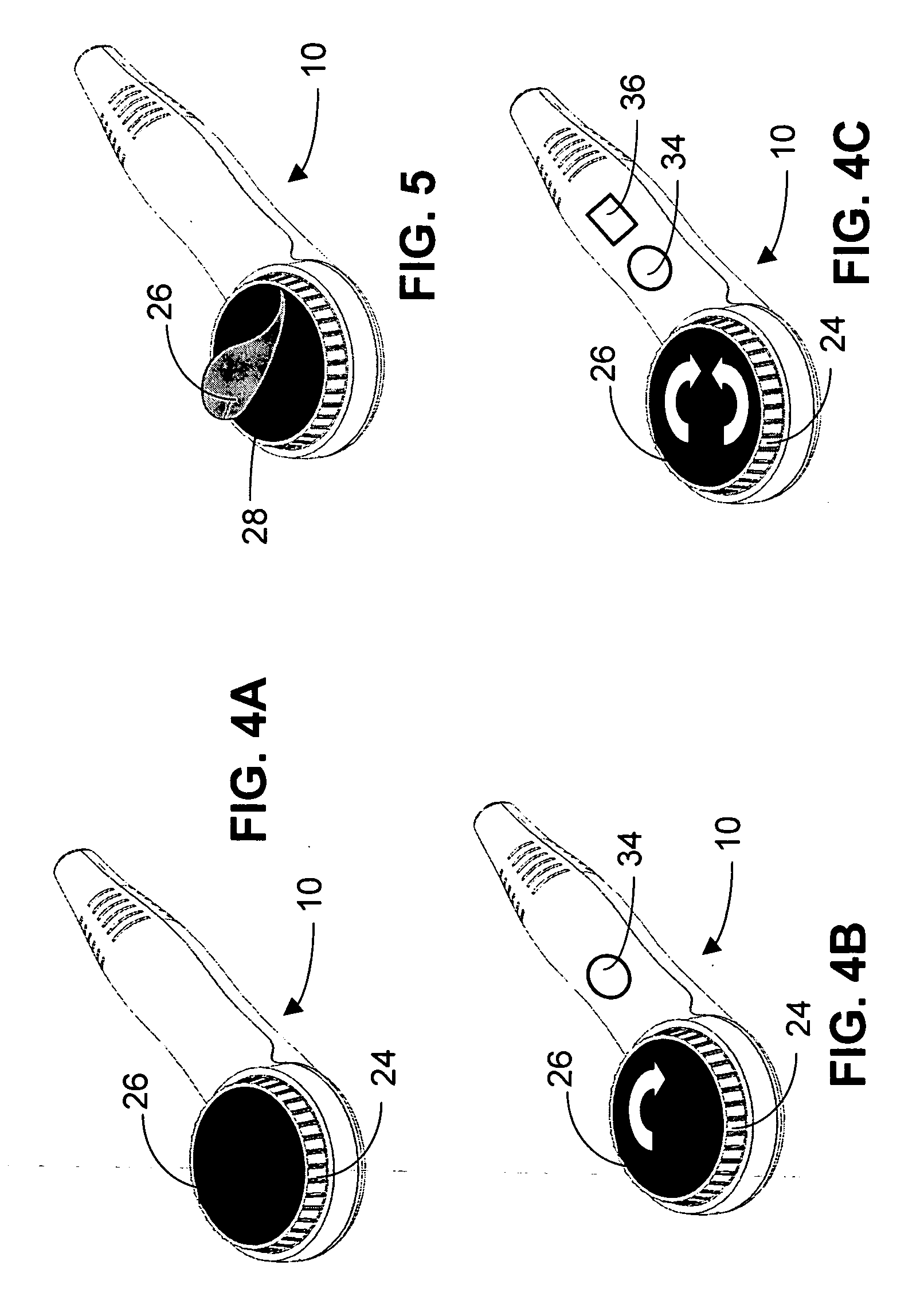
[0037] Referring now to the drawings, FIG. 1 shows a perspective view of an electric hair remover 10 showing a power plug 12, which is plugged in to provide power to the electric hair remover 10. An ac-dc adapter (not shown) converts AC power to DC power for the power plug 12. The handle 14 of the electric hair remover 10 contains a electric motor 16, which drives a gear box 18, as shown in FIG. 11. The handle 14 also has an On / Off switch 20, which turns power on and off to the electric motor 16. The head 22 of the electric hair remover 10 has a circular shape and has a circular base 24, which rotates when the on / off switch 20 is turned on. FIG. 2 is a side view of the electric hair remover 10 showing an abrasive pad 26 removably attached by hooks 28 and loops 30 to the circular base 24, as shown in FIG. 3, which is an enlargement of the circled portion of FIG. 2. In FIG. 3 the loops 30 are shown on the abrasive pad 26 and the hooks 28 are shown on the circular base 24, but the hook...


PUM


Abstract

An electrical device removes body and facial hair and dead skin cells by buffing and abrading by rotating motion. The electrical hair removing device has one, two or three abrasive surfaces for pressing against hairy skin to exfoliate the skin and abrade the hair by automatic and continual electronically controlled rotational movement in the same direction. Hooks and loops removably attach each abrasive surface to a circular base driven in rotation. The two or three abrasive surfaces can be controlled to rotate at different speeds. The two or three abrasive surfaces can also be controlled to rotate in alternating directions and at different speeds.

Description

BACKGROUND OF THE INVENTION [0001] 1. Field of the Invention [0002] This invention relates to a device for removing body and facial hair. More particularly, it relates to a hair remover for removing hair by buffing and abrasion, while simultaneously proving beneficial effects to the skin. [0003] 2. Background Information [0004] The common solution to remove unwanted hair is by using a shaving or cutting device, which can cause irritability and dryness to the skin. The growth rate of the cut hairs can be erratic and the skin can become more sensitive due to cuts and scrapes. In addition, shaving can leave rough stubble. [0005] Epilation devices remove hair by pulling it out. One technique is to apply mastic to the skin and then to allow the mastic to dry. When the mastic is removed the hairs attached to the mastic are pulled out, which is a painful process. Another technique is to merely pull out the hair. In either case the hair must be long enough in length before it can be grasped...

Claims


Application Information

Patent Timeline
IPC IPC(8): B26B19/00
CPCA45D26/0004A45D2200/1018A45D2200/1054
Inventor SUEN, CHI MING
Owner SUEN CHI MING
Why Eureka
Try Eureka