Method for controlling injection of reducing agent in exhaust gas from a combustion engine

Active Publication Date: 2006-06-22
UMICORE AG & CO KG
View PDF7 Cites 39 Cited by
  • Summary
  • Abstract
  • Description
  • Claims
  • Application Information

AI Technical Summary

Benefits of technology

[0010] Accordingly, it is an object of the invention to provide a method and a system for controlling injection of a reductant into a combustion engine exhaust gas. The method is based on simp

Problems solved by technology

However, this means many different measurements and calculations are involved in

Method used


Image

  • Method for controlling injection of reducing agent in exhaust gas from a combustion engine
  • Method for controlling injection of reducing agent in exhaust gas from a combustion engine
  • Method for controlling injection of reducing agent in exhaust gas from a combustion engine

Examples


Example

[0022] A complete combustion of a fuel CHx in combustion engines would be:

CHx+(1+x / 4)O2→CO2+x / 2 H2O  (1)

where O2 is oxygen in combustion air.

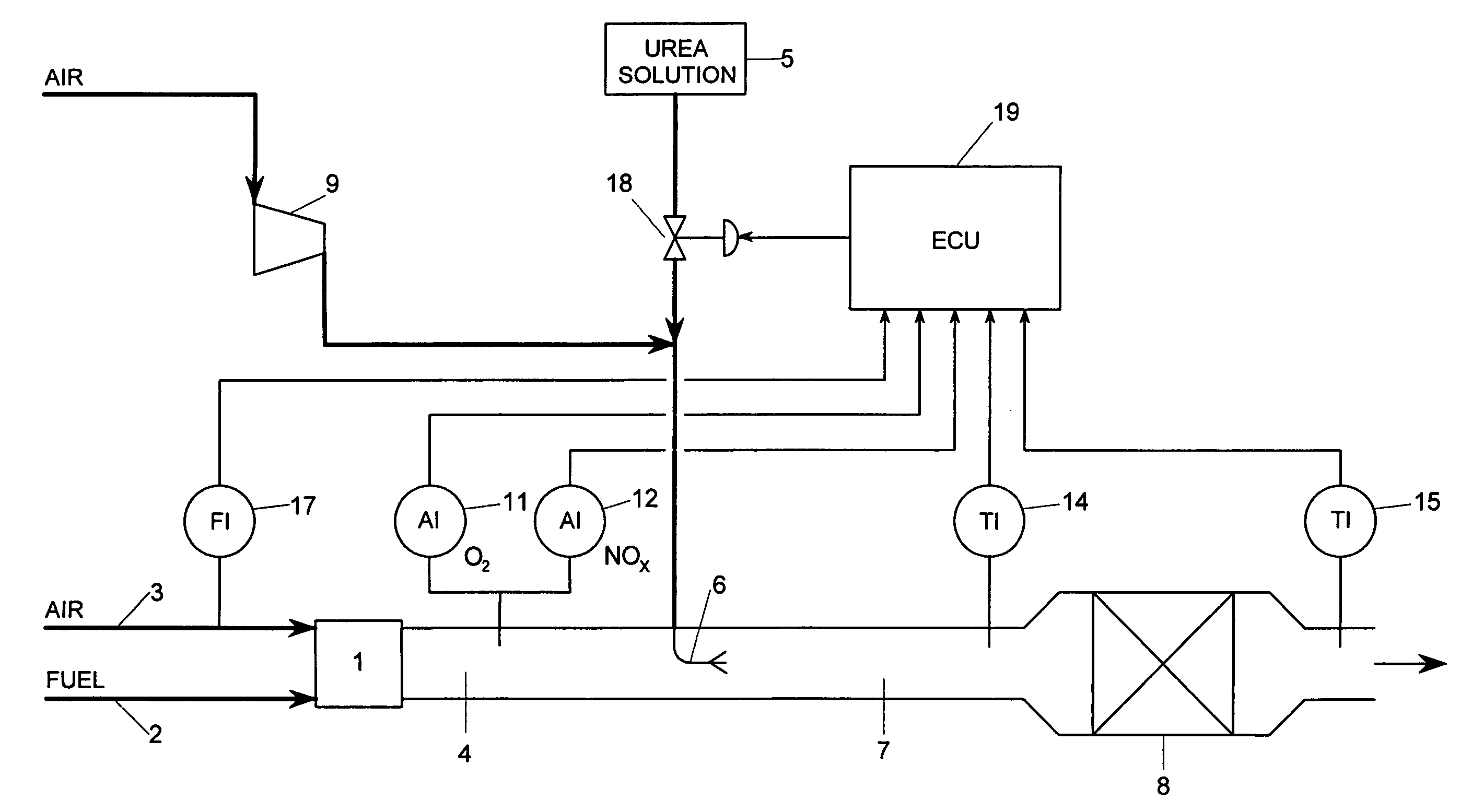
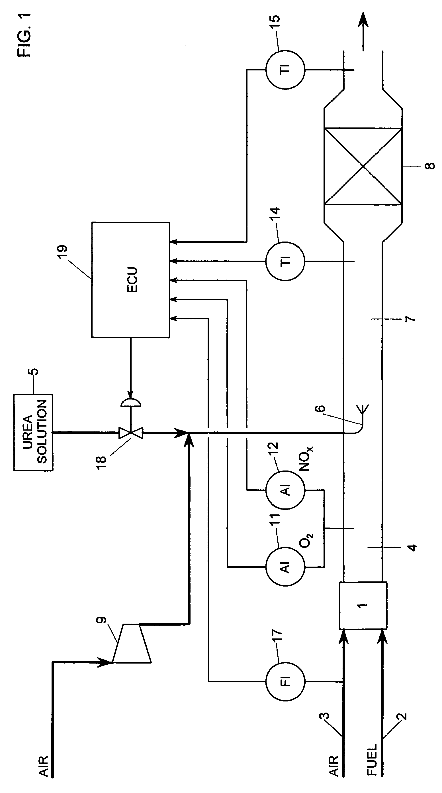
[0023] In diesel engine driven vehicles combustion takes place with a certain amount of excess air. This results in formation of nitrogen oxides, NOx in the exhaust gas, which is a serious pollution for the environment. NOx can be reduced by ammonia, NH3, which however is difficult to store in vehicles, and an aqueous solution of ammonia or urea, H2NCONH2, is therefore preferred as a reducing agent.

[0024] The ammonia is formed when urea decomposes as it is sprayed into the hot exhaust gas according to the following reaction:

H2NCONH2+H2O→2 NH3+CO2  (2)

[0025] The mixture of exhaust gas and reductant, ammonia, then passes over a catalyst where the nitrogen oxides, nitrogen monoxide, NO and nitrogen dioxide, NO2, react with the ammonia to form nitrogen and water according to at least the following reactions:

4 NO+4 NH3+O2⇄4 N2+6 H2O  (3)

and

6 NO2...


PUM


Abstract

The invention relates to a method for controlling injection of a reductant into a NOx containing exhaust gas stream from a combustion engine, where combustion of a known fuel takes place and where the HOx is reduced by selective catalytic reduction, SCR, in the presence of a SCR catalyst, comprising establishing signals related to exhaust gas flow, HOx concentration in the exhaust gas stream upstream of the catalyst, exhaust gas temperature upstream of the SCR catalyst, exhaust gas temperature downstream of the SCR catalyst and to input data for catalyst characteristics. From the signals an adjusted amount of the reductant is calculated by using a calculated amount of reductant and a value d(E*T)/dt, where E is the exhaust gas flow, T is the exhaust gas temperature upstream of the catalyst and t is time.

Description

BACKGROUND OF THE INVENTION [0001] 1. Field of the Invention [0002] The invention relates to a method for controlling a stream containing a component, which takes part in a catalytic reaction and which adsorbes on the catalyst. [0003] The invention is in particular directed to control of injection of a reductant to an exhaust gas, where formed nitroaen oxides are selectively, catalytically reduced and where the reducing component is adsorbed on or desorbed from the surface of the catalyst. Both reducing component and nitrogen oxides must be avoided in the catalyst effluent. [0004] The invention is especially useful in purifying an exhaust gas from combustion engines in vehicles, where nitrogen oxides are reduced by ammonia possibly injected as an aqueous solution of ammonia or urea. [0005] 2. Description of Related Art [0006] Purification of an exhaust gas is already performed in many ways. One way is disclosed in U.S. Pat. No. 6,427,439, where purification of exhaust gas is carried...

Claims


Application Information

Patent Timeline
IPC IPC(8): F01N3/00
CPCB01D53/90B01D53/9409B01D53/9495F01N3/206F01N3/208F01N2560/025F01N2560/026F01N2560/06F01N2560/07F01N2610/02F01N2610/08F01N2610/146Y02T10/24F01N9/00F01N3/08Y02T10/12
Inventor GABRIELSSON, PARGEKAS, IOANNISTHORHAUGE, MAX
Owner UMICORE AG & CO KG
Why Eureka
Try Eureka