Method of doping silica glass with an alkali metal, and optical fiber precursor formed therefrom

a technology of alkali metal and silica glass, which is applied in the field of low-loss optical fiber making, can solve the problems of cristobalite defects in the final glass, the near-total volatilization of the alkali metal dopant, and the difficulty of doping silica glass with alkali metals

Inactive Publication Date: 2006-06-22
CORNING INC
View PDF30 Cites 160 Cited by
  • Summary
  • Abstract
  • Description
  • Claims
  • Application Information

AI Technical Summary

Benefits of technology

[0009] Using the methods disclosed herein, K2O dopant levels between 0.1 and about 5 weight percent have been achieved in consolidated glass tubes. Lower and higher levels can be obtained by manipulating the vapor pressure of the alkali precursor, the diffusion temperature, or the relative concentration of the alkali metal precursor to other alkali sources. Other features and advantages of the invention will be apparent from the following description and the appended claims.

Problems solved by technology

However, it is difficult to dope silica glass with alkali metals using conventional (CVD) processes such as outside vapor deposition (OVD), vapor axial deposition (VAD), and modified CVD (MCVD) wherein soot is a precursor to the final glass.
Thus, the soot produced by these processes tends to crystallize before it can be consolidated into dense glass, resulting in both cristobalite defects in the final glass and near-total volatilization of the alkali metal dopant.
OH− has a deleterious effect on fiber attenuation, particularly when present in the core of the fiber.
Unfortunately, such a drying step would likely strip what little alkali metal remained in the soot.
The approach described in the Ball et al. publication is very promising, but there are challenges to be overcome.
In particular, it is difficult to obtain high doping levels of alkali metal and uniform doping along the length of the tube.
These conditions create problems for uniformity in doping along the length of the tube.

Method used


Image

  • Method of doping silica glass with an alkali metal, and optical fiber precursor formed therefrom
  • Method of doping silica glass with an alkali metal, and optical fiber precursor formed therefrom
  • Method of doping silica glass with an alkali metal, and optical fiber precursor formed therefrom

Examples


example 1

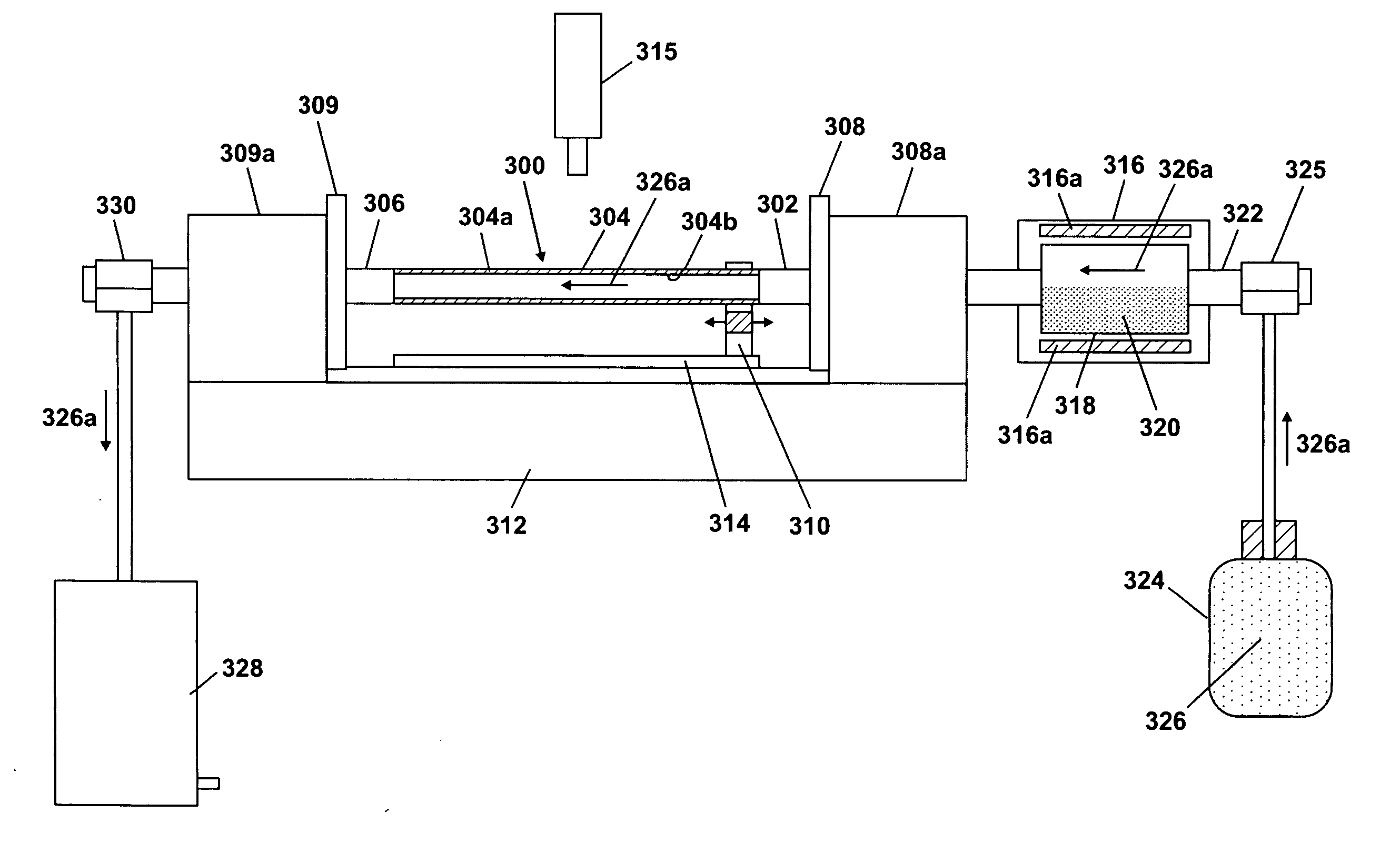
[0029] A powdered mixture is prepared using 12.5 g potassium bromide and 12.5 g potassium superoxide. The powder is preferentially mixed in a water-free atmosphere so as to eliminate hydration of the super oxide. The oxide, peroxide, or super oxide of any other alkali metal could be used in conjunction with an appropriate halide. The powder is loaded into the reservoir (318 in FIG. 3). The powder is heated to approximately 900° C. and allowed to equilibrate for several minutes. A carrier gas is flowed over the surface of the molten salt solution and down through a silica glass tube at a rate of one liter per minute. The carrier gas may be oxygen or other suitably neutral gas. An oxygen-hydrogen burner is used as the heater (310 in FIG. 3). The oxygen and hydrogen flow rates to the heater are adjusted to obtain a wall temperature on the silica glass tube of approximately 2080° C. The heater is then traversed along the silica glass tube, in a direction away from the reservoir, at a ra...

example 2

[0030] A 25 g charge of potassium nitrate is loaded into the reservoir (318 in FIG. 3). The nitrate of any other alkali metal could be used instead if it is desired instead of potassium. The reservoir is heated to approximately 880° C. to melt the nitrate. A carrier gas is flowed over the surface of the molten nitrate and down the length of a silica glass tube. This carrier gas can be oxygen or any neutral gas. The oxygen and hydrogen gas flow rates to the heater (310 in FIG. 3) are adjusted to give a temperature of approximately 2080° C. The heater is then traversed down the silica glass tube, in a direction away from the reservoir, at a rate of approximately 1 cm / s. This accomplishes diffusion doping of the potassium into the surface of the silica glass tube. Additional heater passes may be performed to incorporate more of the potassium into the surface of the silica glass tube and / or drive the alkali metal deeper into the silica glass tube. Using this procedure, peak (i.e. the hi...

example 3

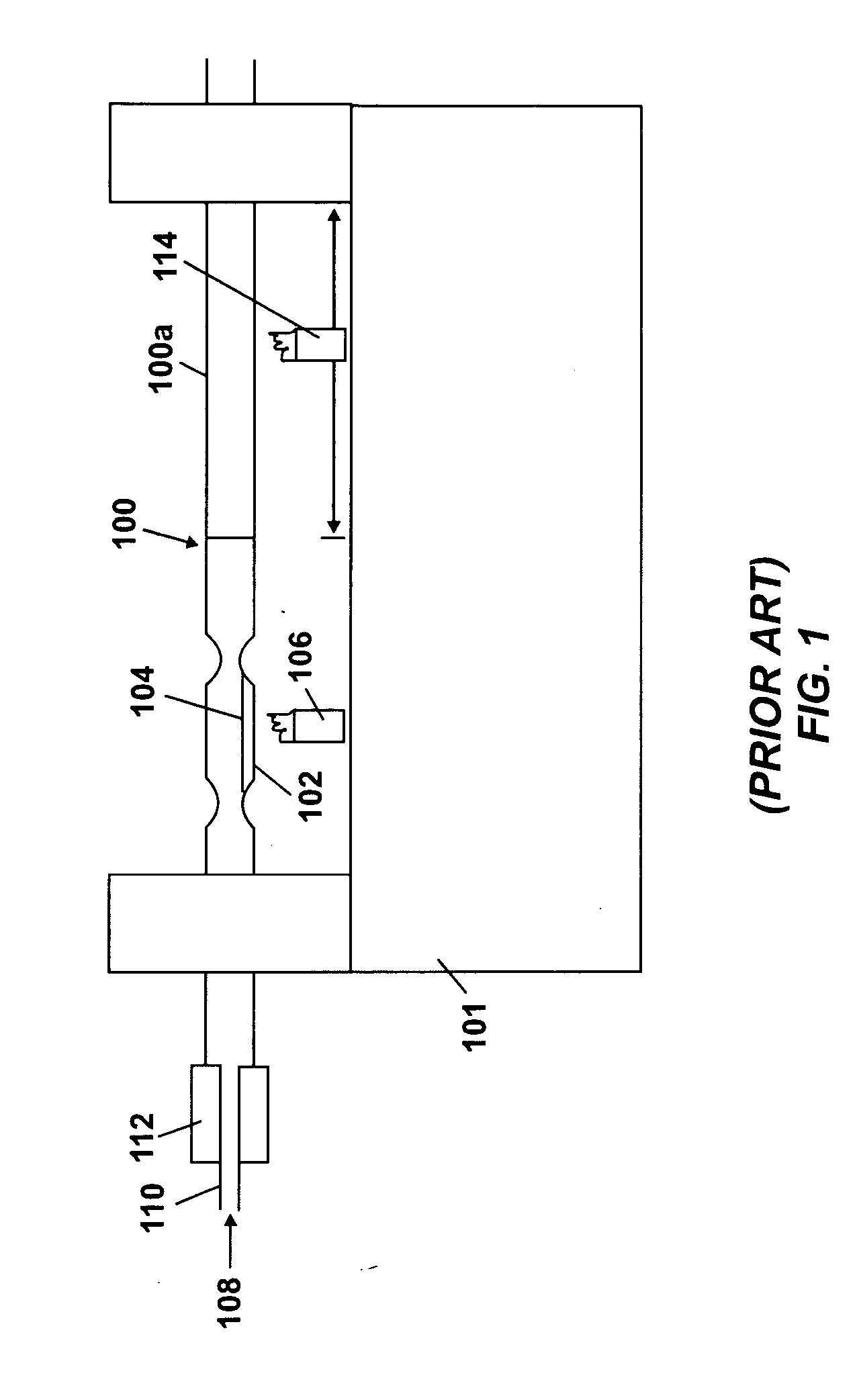
[0031] A 50 g charge of alkali nitrate is placed between constrictions (404a, 408a in FIG. 4) in a silica glass tube. Oxygen and hydrogen gas flow rates to a heater (414 in FIG. 4) are adjusted to levels that produce a tube wall temperature of about 1200° C. Then, the heater is traversed down the length of the silica glass tube at about 10 cm / min to melt the nitrate into a puddle. The gases supplied to the heater are adjusted to raise the wall temperature of the silica glass tube to approximately 2080° C. and a second pass is performed at 1 cm / min. The second slow high temperature pass causes alkali metal to diffuse into the silica glass tube. Additional heater passes may be performed to incorporate more of the potassium into the surface of the silica glass tube and / or drive the alkali metal deeper into the silica glass tube. Using this procedure, peak (i.e. the highest level across the tube wall) levels of about 2 weight percent K2O dopant have been achieved.


PUM

PropertyMeasurementUnit
wavelengthaaaaaaaaaa
temperatureaaaaaaaaaa

Abstract

A method of making an optical fiber precursor includes generating vapors from an alkali metal source comprising compound containing oxygen and one or more alkali metals and applying the vapors to a surface of a glass article comprising silica at a temperature that promotes diffusion of the alkali metal into the surface of the glass article. An optical fiber has a core comprising silica and an alkali metal oxide of the form X2O, where X is selected from the group consisting of K, Na, Li, Cs, and Rb, wherein a concentration of the alkali metal oxide along a length of the core is uniform.

Description

FIELD OF THE INVENTION [0001] The invention relates generally to a method of making a low loss optical fiber. More specifically, the invention relates to a method of doping a silica glass article with an alkali metal and an optical fiber precursor formed from the doped silica glass article. BACKGROUND OF THE INVENTION [0002] Optical fibers in commercial use are mostly based on silica glass. The theoretical minimum attenuation of pure silica is generally accepted to be about 0.15 db / km at 1,550 nm. For optical fibers based on silica glass, attenuation losses have been reduced to the point where most of the remaining attenuation is due to intrinsic scattering within the glass material. It has been demonstrated that intrinsic scattering loss in silica glass can be effectively reduced by doping silica glass with alkali metals, either alone or in combination with other materials such as fluorine. [0003] Optical fibers exhibiting low losses are commonly manufactured by chemical vapor depo...

Claims


Application Information

Patent Timeline
Patent Type & Authority Applications(United States)
IPC IPC(8): C03B37/027C03B32/00
CPCC03B37/01807C03B2201/50C03B2207/85C03B2207/90C03B37/01892C03B2201/03C03B2201/04C03B2201/07C03B2201/075C03B2201/12C03B2201/20C03B2201/28C03B2201/31C03B2201/32C03B2201/54
Inventor ANDERSON, JAMES G.ELLISON, ADAM J. G.SCHIEFELBEIN, SUSAN L.
Owner CORNING INC
Why Eureka
Try Eureka