Magnetization of target well casing strings tubulars for enhanced passive ranging

a casing string and tubular technology, applied in the field of subterranean borehole drilling and surveying, can solve the problems of inability to reliably detect remanent magnetic field, inability to accurately characterize remanent magnetic field, and inability to carefully control the magnetization used for magnetic particle inspection, etc., to achieve simple twinning operation, reduce the diameter, and reduce the effect of twinning

Inactive Publication Date: 2006-06-22
SCHLUMBERGER TECH CORP
View PDF12 Cites 69 Cited by
  • Summary
  • Abstract
  • Description
  • Claims
  • Application Information

AI Technical Summary

Benefits of technology

[0016] Exemplary embodiments of the present invention advantageously combine advantages of active and passive ranging techniques without inheriting disadvantages inherent in such prior art techniques. For example, when the present invention is used, target well casing strings having a strong, highly uniform remanent magnetic field thereabout may be configured. Measurements of the remanent magnetic field strength are thus typically suitable to determine distance to the target well and may be advantageously utilized to drill a twin well along a predetermined course relative to the target well. Such an approach advantageously obviates the need for simultaneous access to the target and twin wells (as is presently required in the above described active ranging techniques). As such, in SAGD applications, this invention eliminates the use of a downhole tractor in the target well and thus may enable smaller diameter, more cost effective production wells to be drilled. Moreover, this invention simplifies twinning operations because it does not typically require lateral alignment of a measurement sensor in the twin well with any particular point(s) on the target well.

Problems solved by technology

While the above mentioned passive ranging techniques attempt to utilize the remanent magnetization in the target well, and thus advantageously do not require positioning an active magnetic or electromagnetic source in the target borehole, there are drawbacks in their use.
For example, the magnetic field strength and pattern resulting from the remanent magnetization of the casing string tubulars is inherently unpredictable for a number of reasons.
First, the remanent magnetization of the target borehole casing results from magnetic particle inspection of the threaded ends of the casing tubulars.
Between casing joints, the remanent magnetic field may be so weak that it cannot be detected reliably.
A second cause of the unpredictable nature of the remanent magnetism is related to handling and storage of the magnetized tubulars.
Finally, the magnetization used for magnetic particle inspection is not carefully controlled because the specific strength of the magnetic field imposed is not important.
These variations cannot be quantified or predicted because no record is generally maintained of the magnetization process used in magnetic particle inspection.
Moreover, the magnetic poles may be distributed randomly within the casing string, resulting in a highly unpredictable magnetic field about the target well.
As such, determining distance from magnetic field strength measurements and / or gradients of the magnetic field strength is problematic.
A related drawback of prior art passive ranging methods that rely on the gradient of the residual magnetic field strength is that measurement of the gradient tends to be inherently error prone, in particular in regions in which the residual magnetic field strength of the casing is small relative to the local strength of the earth's magnetic field.
Reliance on such a gradient may cause errors in calculated distance between the measured and target wells.
While the above described McElhinney technique and other passive ranging techniques have been successfully utilized in commercial well twinning applications, their effectiveness is limited in certain applications.
For example, passive ranging techniques are limited by the relatively weak remanent magnetic field about the target well and by the variability of such fields.
At greater distances (e.g., greater than about 4 to 6 meters) a weak or inconsistent magnetic field about the target well reduces the accuracy and reliability of passive ranging techniques.
Positioning the wells either too close or too far apart may severely limit production, or even result in no production, from the lower well.
Moreover, continuous, simultaneous access to both wells tends to be labor and equipment intensive (and therefore expensive) and can also present safety concerns.
While this problem may be overcome, (e.g., in the method shown on FIG. 1A magnetic field measurements are made at both positive and negative electromagnetic source polarities), it is typically at the expense of increased surveying time, and thus an increase in the time and expense required to drill the upper well.
Third, the above described prior art active ranging methods require precise lateral alignment between the magnetic source deployed in one well and the magnetic sensors deployed in the other.
Misalignment can result in a misplaced upper well, which as described above may have a significant negative effect on productivity of the lower well.
Moreover, the steps taken to assure proper alignment (such as making magnetic field measurements at multiple longitudinal positions in one of the wells) are time consuming (and therefore expensive) and may further be problematic in deep wells.
Moreover, in a few instances, such downhole tractors 32 have been known to become irretrievably lodged in the lower well 30.

Method used


Image

  • Magnetization of target well casing strings tubulars for enhanced passive ranging
  • Magnetization of target well casing strings tubulars for enhanced passive ranging
  • Magnetization of target well casing strings tubulars for enhanced passive ranging

Examples


Embodiment Construction

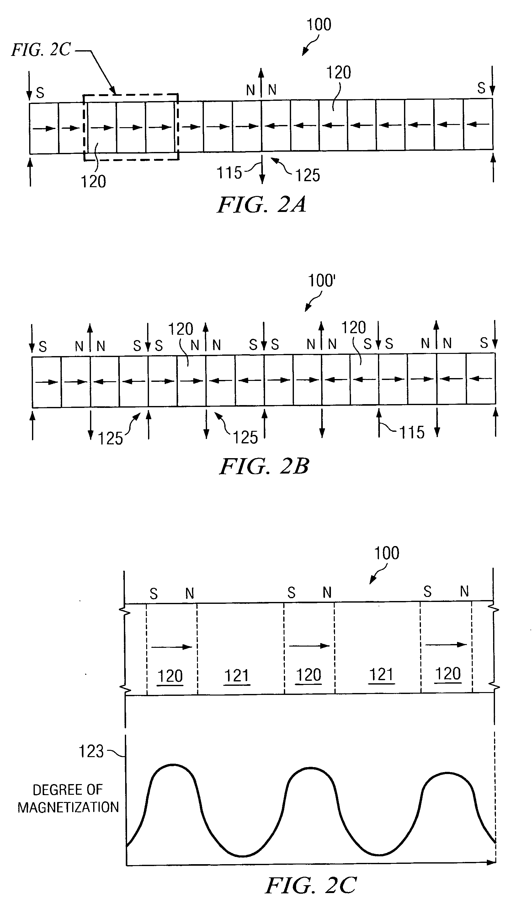
[0031]FIGS. 2A through 2C show schematic illustrations of wellbore tubulars 100 and 100′ magnetized according to exemplary embodiments of this invention. Tubulars 100 and 100′ include a plurality of discrete magnetized zones 120 (typically three or more). Each magnetized zone 120 may be thought of as a discrete cylindrical magnet having a north N pole on one longitudinal end thereof and a south S pole on an opposing longitudinal end thereof. Moreover, the tubulars 100 and 100′ are magnetized such that they include at least one pair of opposing north-north NN or south-south SS poles 125. Such opposing magnetic poles effectively focus magnetic flux outward from or inward towards the tubular as shown at 115 on FIGS. 2A and 2B. In the exemplary embodiment shown on FIG. 2A, tubular 100 includes 16 discrete magnetized zones 120 configured such that tubular 100 also includes a single pair of opposing NN poles 125 located at about the midpoint along the length thereof. Alternative embodimen...


PUM


Abstract

A method for magnetizing a wellbore tubular is disclosed. The method includes magnetizing a wellbore tubular at three or more discrete locations on the tubular. In exemplary embodiments the magnetized wellbore tubular includes at least one pair of opposing magnetic poles located between longitudinally opposed ends of the tubular. Wellbore tubulars magnetized in accordance with this invention may be coupled to one another to provide a magnetic profile about a section of a casing string. Passive ranging measurements of the magnetic field about the casing string may be utilized to survey and guide drilling of a twin well. Such an approach advantageously obviates the need for simultaneous access to both wells.

Description

RELATED APPLICATIONS [0001] This application claims priority to commonly-invented, commonly-assigned, co-pending Canadian patent application serial no. 2,490,953, filed Dec. 20, 2004. FIELD OF THE INVENTION [0002] The present invention relates generally to drilling and surveying subterranean boreholes such as for use in oil and natural gas exploration. In particular, this invention relates to a method of magnetizing a string of wellbore tubulars to enhance the magnetic field about a target borehole. Moreover this invention also relates to a method of passive ranging to determine bearing and / or range to such a target borehole during drilling of a twin well. BACKGROUND OF THE INVENTION [0003] The use of magnetic field measurement devices (e.g., magnetometers) in prior art subterranean surveying techniques for determining the direction of the earth's magnetic field at a particular point is well known. The use of accelerometers or gyroscopes in combination with one or more magnetometers...

Claims


Application Information

Patent Timeline
Patent Type & Authority Applications(United States)
IPC IPC(8): E21B47/00E21B31/06E21B47/0228E21B47/024E21B47/09
CPCE21B47/02216E21B47/0228G01V3/26
Inventor MCELHINNEY, GRAHAM A.
Owner SCHLUMBERGER TECH CORP
Why Eureka
Try Eureka