Method and system for monitoring partial discharge in gas-insulated apparatus

a gas-insulated apparatus and partial discharge technology, applied in the direction of fault location, fault location by conductor type, instruments, etc., can solve the problems of difficult exact check and extremely low possibility of dielectric breakdown, and achieve the effect of drastically reducing maintenance costs

Active Publication Date: 2006-06-22
JAPAN AE POWER SYST
View PDF13 Cites 38 Cited by
  • Summary
  • Abstract
  • Description
  • Claims
  • Application Information

AI Technical Summary

Benefits of technology

[0030] The present invention achieves an effect that the condition of insulation failure in a gas-insulated apparatus can be checked exactly and that guidance on maintenance can be provided based on the obtained risk level. In other words, it becomes po

Problems solved by technology

In case of a defect such as float electrode, however, the possibility of dielectric breakdown can be extremely low even if a high signal in excess of several-thousand pC is caused.
In other words, evaluation based only on the discharge level is not enough to evaluate the actual risk condition of apparatus and exact evaluation of the risk conditi

Method used


Image

  • Method and system for monitoring partial discharge in gas-insulated apparatus
  • Method and system for monitoring partial discharge in gas-insulated apparatus
  • Method and system for monitoring partial discharge in gas-insulated apparatus

Examples


embodiment 1

[0065]FIG. 30 shows a construction of a gas-insulated switching apparatus to which the present invention applies, showing a system configuration capable of continuous monitoring. The gas-insulated switching apparatus is a metallic container with ground potential, which contains a circuit breaker 55, disconnecting switch 54, grounding switch 53, bus 57, arrestor 58, current transformer 52, and transformer 56, and is filled with SF6 gas having excellent insulation performance and current limiting performance.

[0066] Power is led into the apparatus from an overhead wire or power cable via a bushing 51 or cable head, and supplied to the bus 57, disconnecting switch 54 and circuit breaker 55. The arrestor 58 for controlling overvoltage due to lightning is installed near the bushing for incoming power, and the transformer 56 for measuring the voltage and current transformer 52 for measuring the current are installed at appropriate positions.

[0067] Since existence of any insulation failur...

embodiment 2

[0122] A case where the defect type is protrusion has been described in Embodiment 1. Next, another defect size calculation in case of different defect type is described hereunder.

[0123] Typical defect type in a gas-insulated apparatus is defect caught on spacer surface. This is a case where some mixed metallic particle is caught on the spacer for supporting the center conductor in FIG. 30.

[0124]FIG. 32 shows an example particle caught on the surface of the spacer. In case a particle 31 is caught on the surface of the spacer 6, the electromagnetic wave of the caused partial discharge 71 is sensed by the sensor installed inside the gas-insulated apparatus. As shown there, partial discharge 71 is caused at the end of the particle 31 on the surface of the spacer 6.

[0125] The partial discharge 71 caused progresses along the spacer surface. That is to say, in evaluating the signal intensity (discharge level) of the partial discharge 71 from the foreign substance 31 caught on the space...

embodiment 3

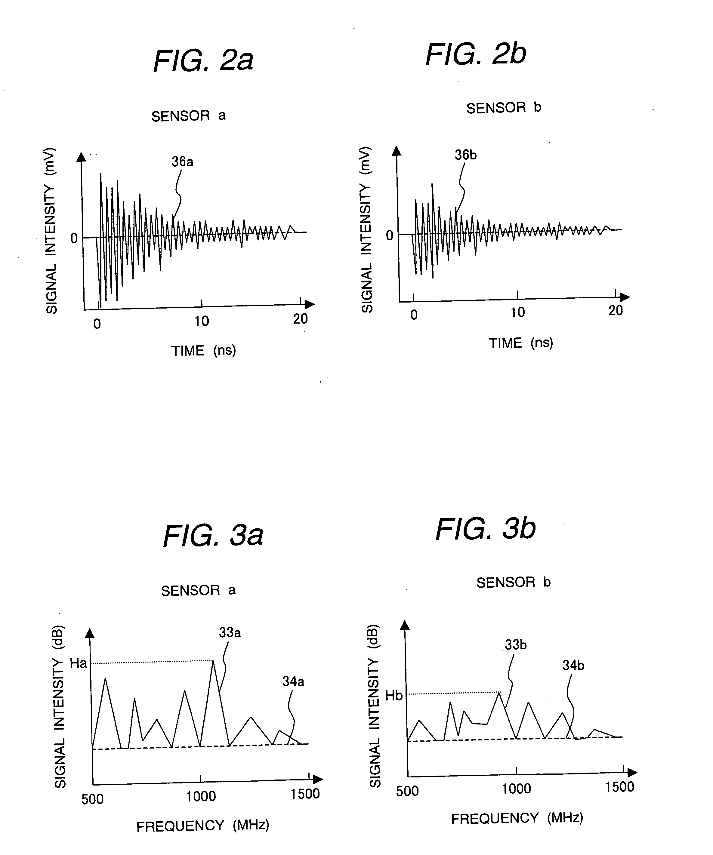
[0130] In estimating the defect size in Embodiment 1 and Embodiment 2, the frequency of the sensed signal is analyzed to obtain the maximum signal intensity (FIG. 3) in the frequency band from 500 MHz to 1500 MHz and the actual discharge intensity is calculated from it. This, however, does not consider the frequency sensed in the frequency band from 500 MHz to 1500 MHz. Since the rising time of partial discharge is very sharp such as in ns (nanosecond) as explained previously, it contains signal components reaching the high-frequency band.

[0131]FIG. 25 shows the frequency characteristic of partial discharge signal. The frequency characteristic in 500 MHz to 1500 MHz exhibits higher signal intensity at lower frequency. This curve can be expressed by Formula (4) in terms of the frequency f, (where C is a constant).

y=−20×log(f)+C  (4)

[0132] In other words, same discharge results in different signal intensity depending upon the frequency band and, therefore, the frequency to be sensed ...


PUM


Abstract

A gas-insulated apparatus is equipped inside with multiple sensors for sensing a partial discharge signal caused by a foreign substance, and a frequency analyzing section for analyzing the frequency of the sensed partial discharge signal. A defect type judging section estimates the defect type of the foreign substance from the signal obtained through the frequency analysis or from the voltage phase distribution of partial discharge synchronized with the frequency of the voltage applied to the gas-insulated apparatus, and a location determining section estimates the defect location and signal intensity from the multiple partial discharge signals. A defect size calculating section estimates the defect size for each defect type from the signal intensity and field distribution at the defect location. Dielectric breakdown risk evaluation is performed based on the defect size and type, and the insulation failure risk is diagnosed from the partial discharge.

Description

CLAIM OF PRIORITY [0001] The present application claims priority from Japanese application serial No.2004-363973, filed on Dec. 16, 2004, the contents of which is hereby incorporated by references into this application. BACKGROUND OF THE INVENTION [0002] 1. Field of the Invention [0003] The present invention relates to a partial discharge monitoring method and system to diagnose failure condition of a gas-insulated apparatus by sensing partial discharge caused inside the gas-insulated apparatus. [0004] 2. Prior Art [0005] As power supply increases and substation facilities become more compact recently, gas-insulated apparatus filled with high-pressure SF6 gas of which electrical insulation performance, current limiting performance and reliability are very excellent has been popularized. [0006] While SF6 gas filled in a gas-insulated apparatus exhibits excellent insulation characteristic, the insulation characteristic degrades drastically in a non-uniform field. This is mostly caused...

Claims


Application Information

Patent Timeline
IPC IPC(8): G01R31/08G01R31/12
CPCG01R31/085G01R31/1254G01R31/12
Inventor KATO, TATSUROMORIYAMA, TOMOHIROENDO, FUMIHIRO
Owner JAPAN AE POWER SYST
Why Eureka
Try Eureka