Coated article, manufacturing method therefor and coating apparatus

Inactive Publication Date: 2006-06-22
JTEKT CORP
View PDF14 Cites 12 Cited by
  • Summary
  • Abstract
  • Description
  • Claims
  • Application Information

AI Technical Summary

Benefits of technology

[0035] In an embodiment, the thickness of the coating film is set to 100 μm to 250 μm. As a result, working noise (tap tone) of this coated article can be reduced to a specified desired value or lower, and wear can also be reduced. With the film thickness below 100 μm, working noise (tap tone) would be over the specified value. With the film thickness over 250 μm, not only working noise would not be significantly reduced but

Problems solved by technology

In the case where such a resin coating is formed by fluidization dipping process, the resulting coating become large in thickness because of large thermal capacity of the articles (such as gears etc.), while an attempt to make the coating into a thin film would cause the coating levelness to lower, making it difficult to form a uniform coating with high precision.
However, this method involves the machining process at the crests and troughs, or roots, of teeth of gears, resulting in not only lowered production efficiency but also increased cost.
With this method, unfortunately, larger-sized gears or spline shafts would take prolonged time for elevation of the object temperature by an oven.
Moreover, since the temperature elevation begins with the surface of the powder bed in the oven, rapid heating, if applied, would involve scaling and/or flaking, namely detachment, of th

Method used


Image

  • Coated article, manufacturing method therefor and coating apparatus
  • Coated article, manufacturing method therefor and coating apparatus
  • Coated article, manufacturing method therefor and coating apparatus

Examples


Example

EXAMPLE

[0088] The present invention is described below in more detail based on an example thereof, but the present invention is not limited by the example.

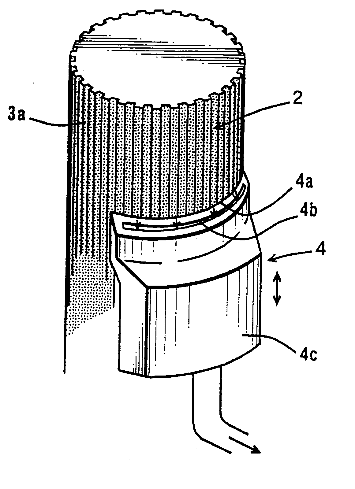
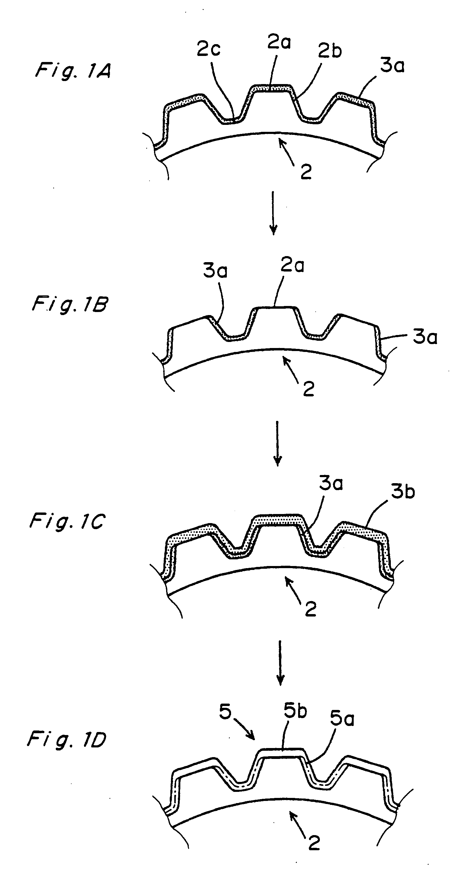
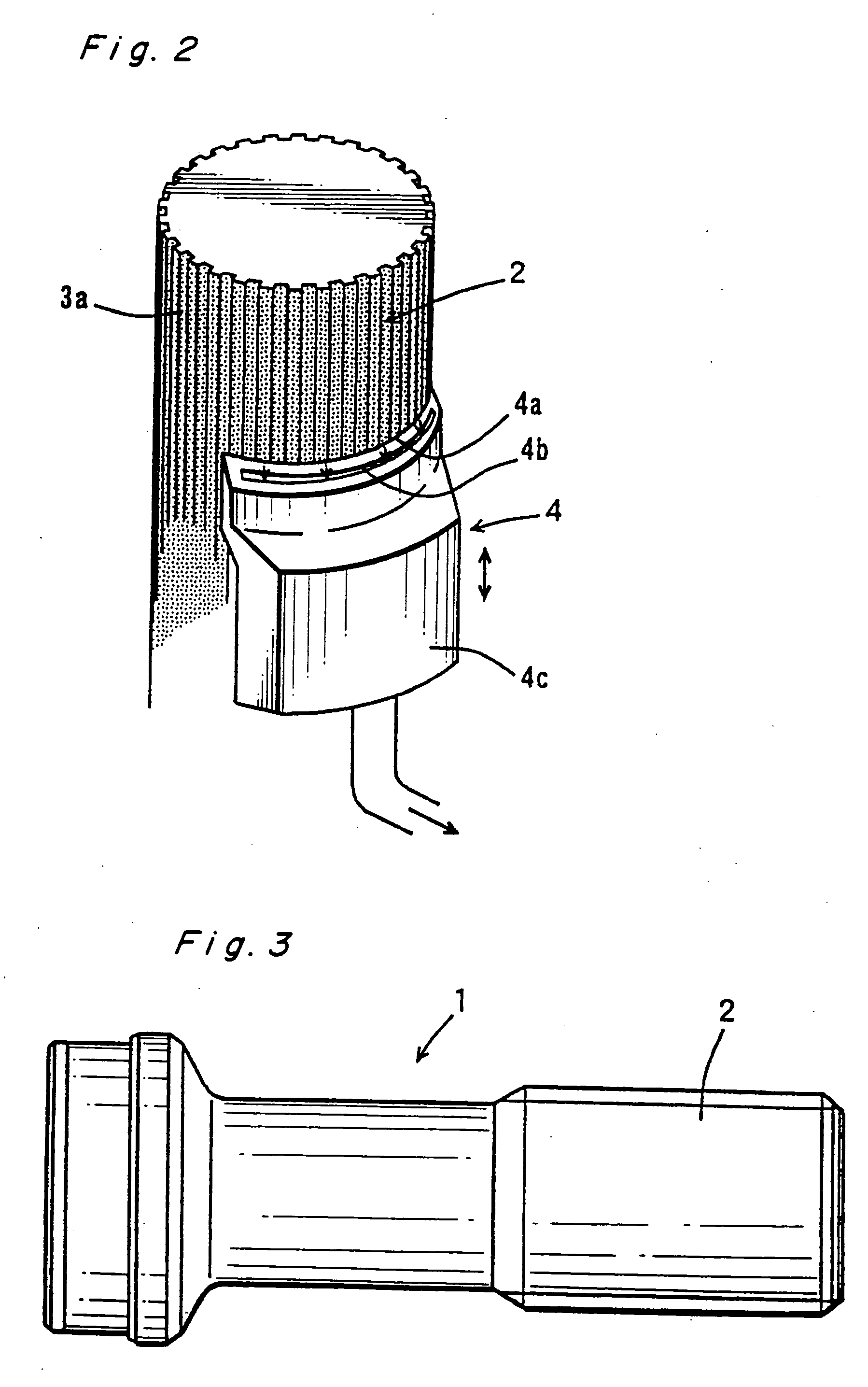
[0089] While a spline shaft was being rotated, a 12-nylon-based powder coating material (mean particle size: 32 μm) was applied to the spline shaft at its toothed portion (namely a keyway section, where deddendum circle diameter: 46 mm φ, length: 80 mm, keyway count: 20) for 20 seconds by electrostatic powder coating by using an electrostatic spray gun, by which a primary powder bed was formed. While a sheet curved in correspondence to the curvature of the addendum circle was being moved upward along the axis of the spline shaft, the primary powder bed at the tooth crests was scraped off, and moreover removed by suction. Then, by using the electrostatic spray gun and the powder coating material, the toothed portions of the spline shaft were subjected to a 20-second electrostatic powder coating process, by which a secondary powde...

Example

[0093] Next, with reference to FIGS. 5A, 5B and 5C in this order, a second embodiment of the manufacturing method for coated articles according to the present invention will be described.

[0094] First, as shown in FIG. 5A, a tip portion 53, indicated by broken line, of each of teeth 54 of a spline shaft 51 as an article to be coated is cut off by a specified depth. This cutting depth is set to such a value as can compensate a thickness difference by which in the subsequent electrostatic deposition step, thickness of a powder deposit at the tip portions 53 will be larger than thickness of a powder deposit at sides 57 and troughs or roots 59 of the teeth. For example, this cutting depth is such that the tooth height is lowered by an amount corresponding to 20% of the coating film thickness, although the cutting depth. may be set within such a range that the tooth height is lowered by an amount corresponding to 10%-60% of the coating film thickness, depending on the shape of the teeth....


PUM


Abstract

After forming a primary powder bed at a toothed portion of an article, such as a gear or a spline shaft, by electrostatic powder coating process, the powder bed is removed from crests of teeth in the toothed portion by a specified thickness by scraping it off while sucking up the scraped powder. Next, the electrostatic powder coating process is performed again to form a secondary powder bed over the entire surface of the toothed portion. Then, the primary and secondary powder beds are melted or fused by induction heating to thereby form a coating film of a substantially uniform thickness.

Description

BACKGROUND OF THE INVENTION [0001] The present invention relates to a method for forming a coating film at uniform thickness on metallic articles having projections and depressions defined by or defining the projection, particularly gears and spline shafts. The present invention also relates to a method of manufacturing coated articles such as coated gears and spline shaft, and to a coating apparatus. [0002] Metallic spline shafts and metallic gears for use in motive power or motion transmission are formed with a resin coating to impart thereto wear resistance, cushioning property, soundproof property or muffling property. In the case where such a resin coating is formed by fluidization dipping process, the resulting coating become large in thickness because of large thermal capacity of the articles (such as gears etc.), while an attempt to make the coating into a thin film would cause the coating levelness to lower, making it difficult to form a uniform coating with high precision....

Claims


Application Information

Patent Timeline
IPC IPC(8): B05D1/04H05C1/00
CPCB05D1/04B05D3/0281B05D3/12B05D7/14B05D7/542F16C3/03F16D3/06F16D2250/00F16D2300/10
Inventor KITAHATA, KOUJITOJO, TAKESHIKOYAGI, KATSURAKUROKAWA, TAKANORISUEHIRO, ATSUONIIDE, YOSHIFUMITANIGUCHI, KOUICHINAKAMURA, SHINGO
Owner JTEKT CORP
Why Eureka
Try Eureka