Reinforced matrix composite containment duct

Active Publication Date: 2006-06-22
GENERAL ELECTRIC CO
View PDF64 Cites 16 Cited by
  • Summary
  • Abstract
  • Description
  • Claims
  • Application Information

AI Technical Summary

Benefits of technology

[0015] The method and tool of the present invention is particularly suitable for fabrication of large composite parts, including cylindrical parts having a diameter of greater than about 5 feet, including parts having a diameter of about 10 feet. An advantage of the present invention is that the tool and method are capable of fabricating large parts, such as large composite fan casings, while maintaining the containment properties, the lighter weight, the high strength and the substantial uniformity of composition and properties throughout the part.
[0016] The method and tool of the present invention provides a method for manufacturing fiber reinforced matrix composites having the shape of the finished product, requiring little or no trimming prior to installation. An advantage of the present invention is that the tool and method produce parts that require little or no additional steps prior to installation and use. The reduction or elimination of addition steps decrease cost and time for fabrication.
[0017] The method and tool of the present invention provides a method for manufacturing fiber reinforced matrix composites that has a high uniformity of composition and less defects, such as porosity and wrinkling. Uniform composition and less defects allows for less scrapped and/or repaired parts. Less scrapped and/or repaired parts allows for fabrication of composite parts, including large composite parts, wit

Problems solved by technology

However, steel is relatively heavy and has been replaced with lighter weight high strength materials, such as aluminum or titanium.
Graphite fibers embedded within a polyimide resin have drawbacks, including difficulty molding the material into parts, high porosity, microcracking, delamination, and expensive equipment and processes.
The drawbacks of the cross-over tool and method disclosed in the '621 Patent includes a complicated process, and an expensive tool that is difficult to use.
The '435 Patent process has the drawback that it only debulks the material and does not pull taut the fabric to provide f

Method used


Image

  • Reinforced matrix composite containment duct
  • Reinforced matrix composite containment duct
  • Reinforced matrix composite containment duct

Examples


Example

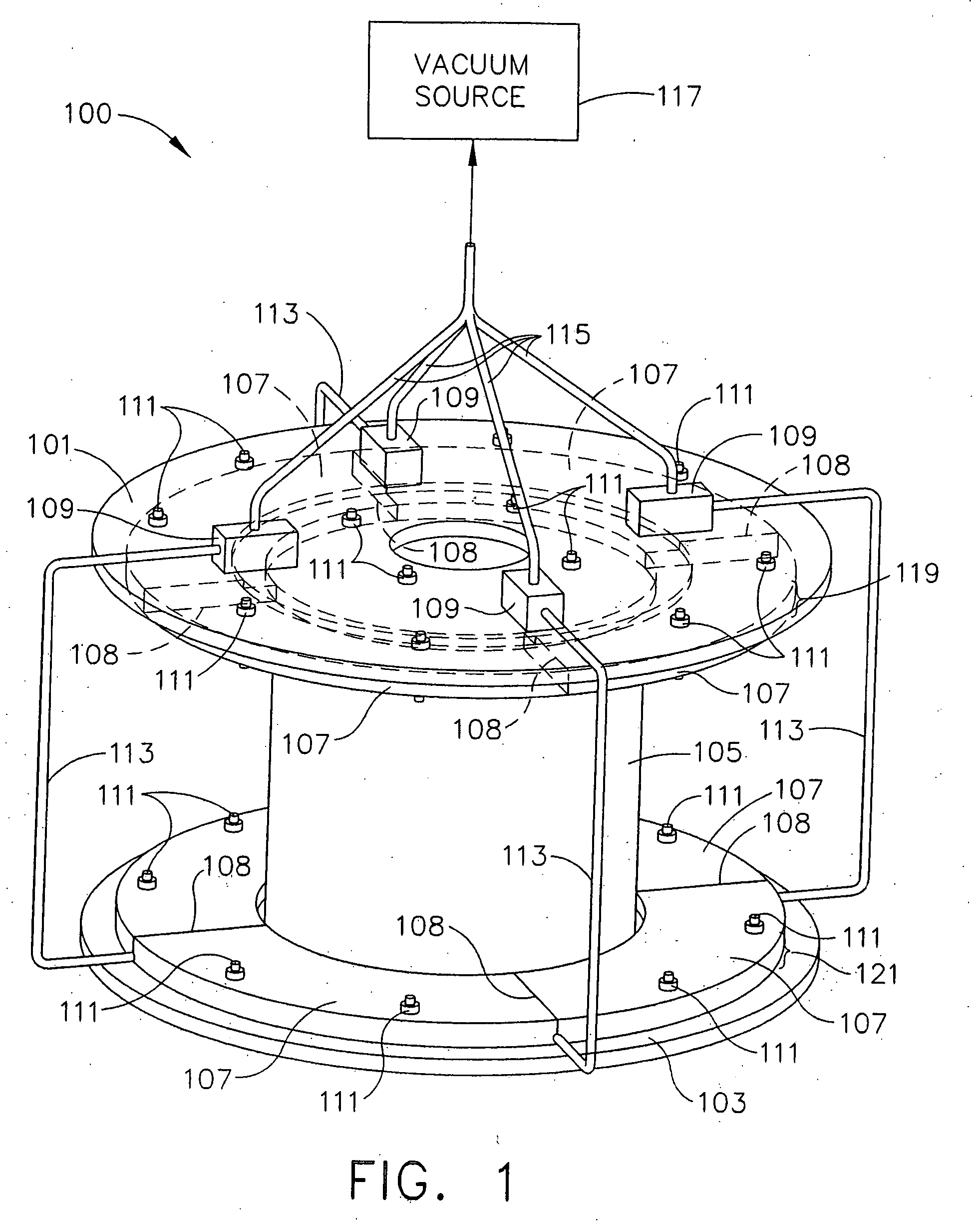
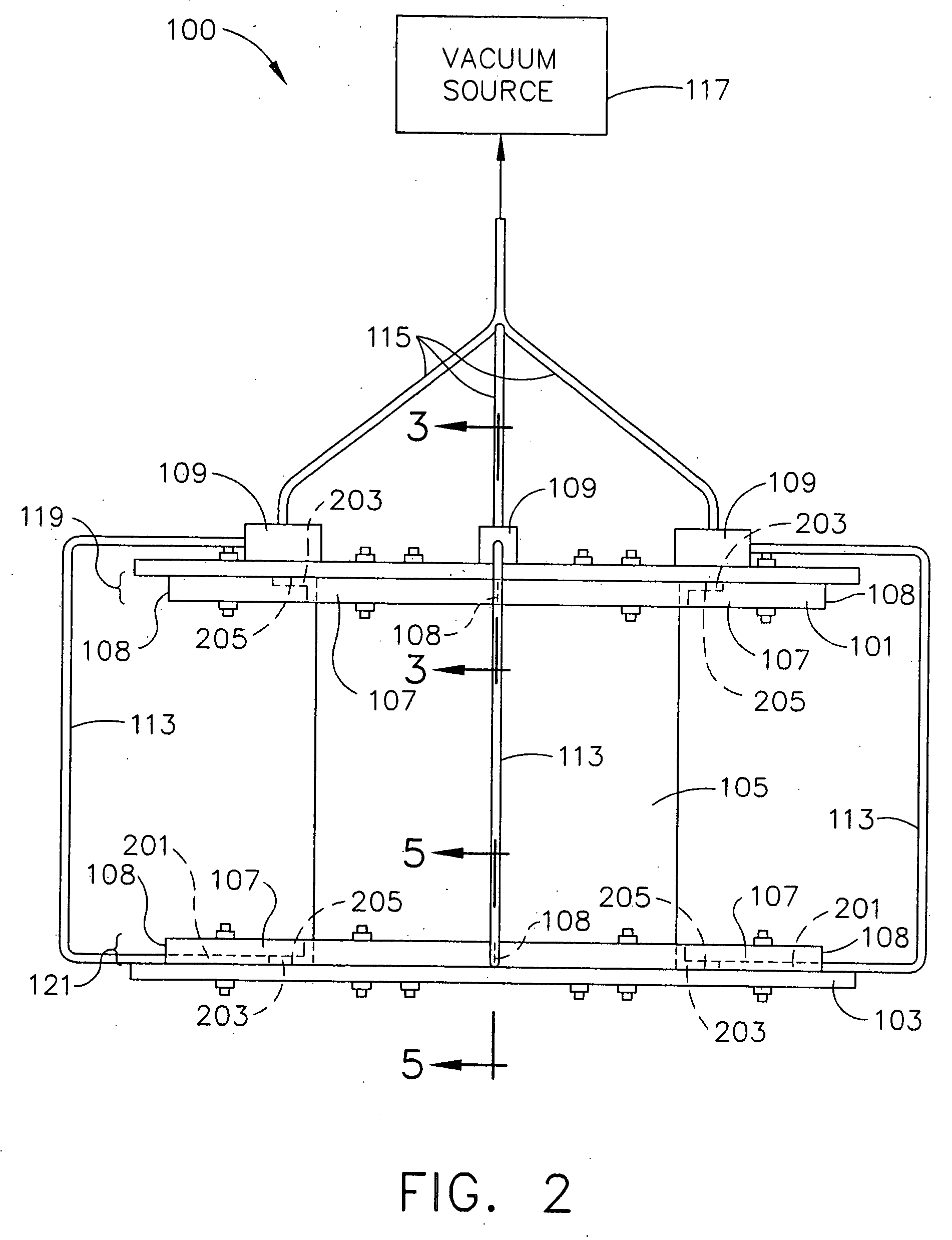
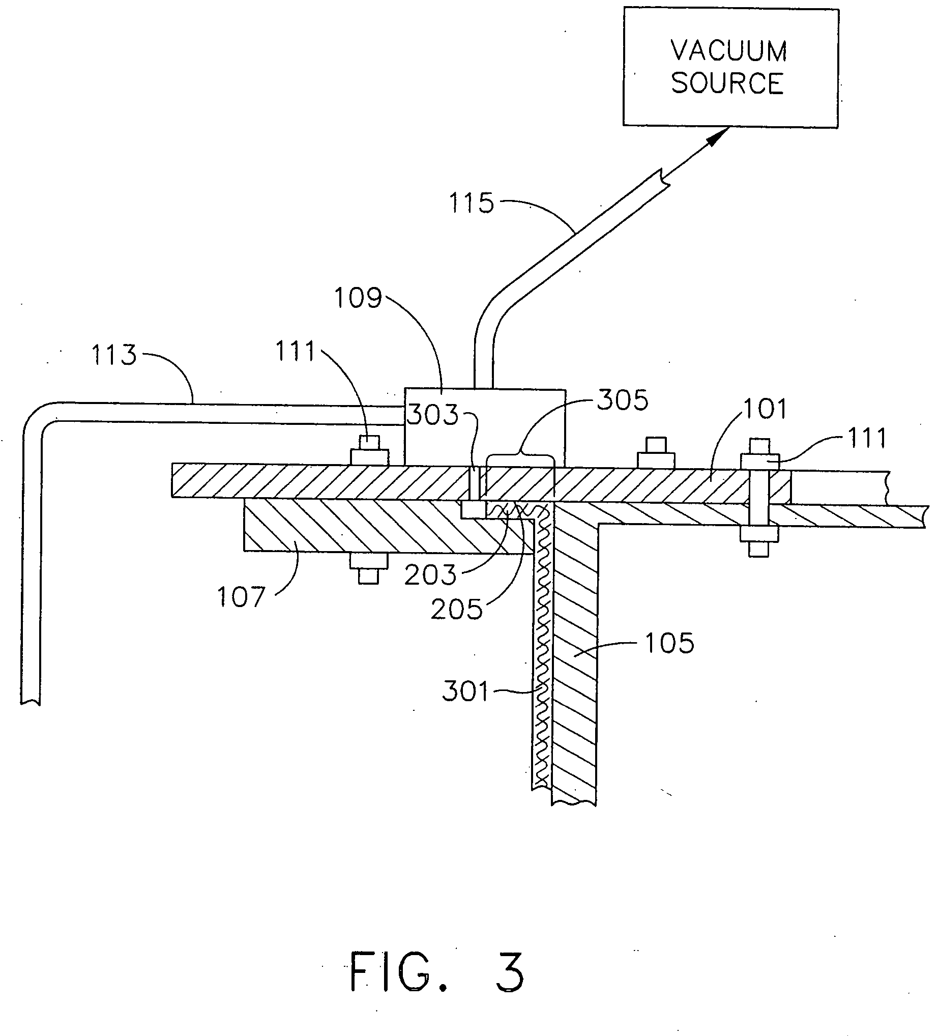
[0027]FIG. 1 shows a composite duct-forming tool 100 according to the present invention. The tool 100 includes a substantially cylindrical body 105. A first endplate 101 and a second endplate 103 are positioned adjacent to the opposed planar ends of the body 105. The body 105 and first and second endplates 101 and 103 are fabricated from a material having a greater thermal coefficient of expansion than the workpiece held by the tool 100. Material for the body 105 and first and second endplates 101 and 103 include, but are not limited to, metals or alloys. Suitable materials for the body 105 include aluminum and steel. The first endplate 101 is fastened to the body 105 with stress relief fasteners 111. The second endplate 103 adjacent to the body 105 is attached to the body 105. The body 105 has a substantially cylindrical geometry. The substantially cylindrical body 105 preferably tapers from a smaller diameter adjacent to the first endplate 101 to a larger diameter at the second en...


PUM

PropertyMeasurementUnit
Fractionaaaaaaaaaa
Fractionaaaaaaaaaa
Fractionaaaaaaaaaa

Abstract

A reinforced matrix composite containment duct for gas turbine engines comprising a reinforced matrix composite containment duct having high strength integral flanges and pre-stressed reinforcing fibers, the reinforced matrix composite having uniform distribution of matrix material; and the reinforced matrix composite having less than or equal to 2.5% void space.

Description

CROSS-REFERENCE TO RELATED APPLICATIONS [0001] The Application is related to application Ser. No. ______ Attorney Docket No. 154236 (07783-0209), filed contemporaneously with the Application on Dec. 22, 2004 entitled “AN APPARATUS FOR FABRICATING REINFORCED COMPOSITE MATERIALS” assigned to the assignee of the present invention and which is incorporated herein by reference in its entirety, and to application Ser. No. ______ Attorney Docket No. 133632 (07783-0213), filed contemporaneously with the Application on Dec. 22, 2004 entitled “A METHOD FOR FABRICATING REINFORCED COMPOSITE MATERIALS” assigned to the assignee of the present invention and which is incorporated herein by reference in its entirety.FIELD OF THE INVENTION [0002] This invention relates to reinforced matrix composite materials. In particular, the present invention involves reinforced matrix composite materials for gas turbine engine containment ducts. BACKGROUND OF THE INVENTION [0003] Aircraft engine design continual...

Claims


Application Information

Patent Timeline
IPC IPC(8): D04H13/00D04H5/00
CPCY02T50/672B29C70/465B29L2031/7504F01D21/045F05D2300/702F05D2300/614Y02T50/60Y10T428/249924
Inventor BLANTON, LEE ALANMEIBERS, GREGORY JOSEPHWHITEKER, STEPHEN MARKFAIRBANKS, ROBERT PAULPRICE, RICHARD THOMASRONK, WARREN ROSAL
Owner GENERAL ELECTRIC CO
Why Eureka
Try Eureka