Method of increasing toughness of heat-affected part of steel product welded joint

a technology of heat-affected parts and welded joints, which is applied in the direction of metal extrusion, non-electric welding apparatus, metal-working apparatus, etc., can solve the problems of large installation costs and process loads, excess welding work such as grinding work, and the crystal grains are not made finer by re-heating, etc., to achieve the effect of improving the toughness of the heat-affected zon

Inactive Publication Date: 2006-06-29
NIPPON STEEL CORP
View PDF7 Cites 16 Cited by
  • Summary
  • Abstract
  • Description
  • Claims
  • Application Information

AI Technical Summary

Benefits of technology

The present invention provides a method for improving the toughness of a heat affected zone in a multi-layer welded joint, fillet welded joint, or one-pass or several-pass large heat input welded joint of a steel plate. The method involves subjecting the surface of the heat affected zone to impacts by an ultrasonic vibration tool or shot peening by ultrasonic vibration steel balls to create an average of longitudinal axis of crystals up to a depth of 2 mm or more from the surface of the steel plate in the microstructure adjacent to a fusion line of a weld metal and a steel plate matrix. The resulting improvement in toughness can be achieved by impacts at a depth of ¼ of a thickness t from the surface of the steel plate. Additionally, supplemental heating of the steel plate before or during the impacts can further enhance the toughness improvement.

Problems solved by technology

However, the HAZ formed by a last pass near the surface of the steel plate is not subjected to a subsequent welding pass, therefore the crystal grains are not made finer by re-heating.
By such a measure, however, excess welding work becomes necessary such as grinding work etc.
Therefore, there was a problem that the installation costs and a process load were large, so this was not realistic.
Therefore, there was the same problem as that of a multi-layer welded joint.
However, the HAZ microstructure easily become coarse when the amount of heat input of the welding is large.
Therefore, if restricting the amount of heat input or improving the welding efficiency by making the groove narrower and nearer to vertical, the steel plate matrix is not sufficiently melted and the weld metal ends up solidifying earlier.
Therefore, undercut in welding easily occurs at the toe portion.
This zone becomes a stress concentration site and becomes a fracture initiation point, so there arises a problem of a remarkable drop in the fracture toughness.
However, this prior art is a method of improving the fatigue strength by impacts by an ultrasonic vibrator and does not discloses anything about increasing the refinement of the microstructure of the HAZ or improving the toughness by pressing together the poorly fused parts of the object of the present invention.

Method used


Image

  • Method of increasing toughness of heat-affected part of steel product welded joint
  • Method of increasing toughness of heat-affected part of steel product welded joint
  • Method of increasing toughness of heat-affected part of steel product welded joint

Examples


examples

[0052] Examples of the method of improvement of toughness of a heat affected zone in a welded joint of a steel plate of the present invention will be shown below.

second examples

First and Second Examples

[0053] Note that, Table 1 and Table 2 give examples corresponding to the first and second embodiments, and Table 3 and Table 4 give examples corresponding to the third embodiment.

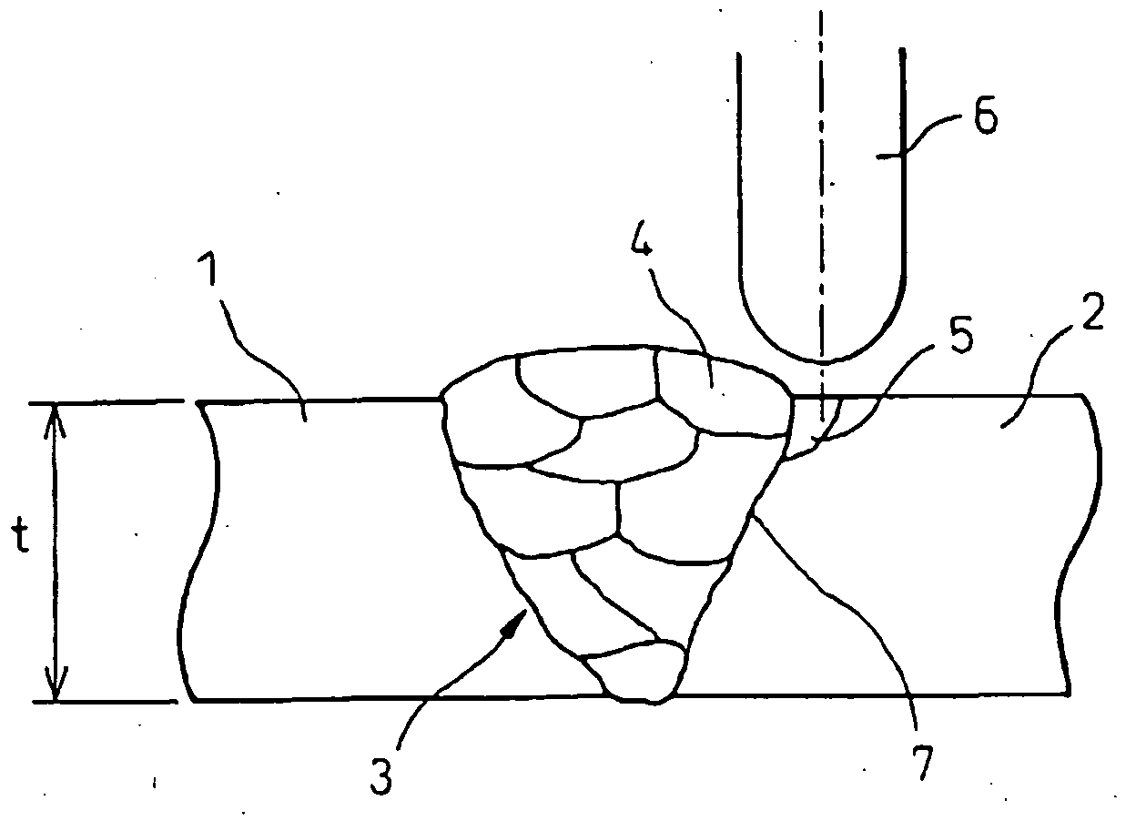
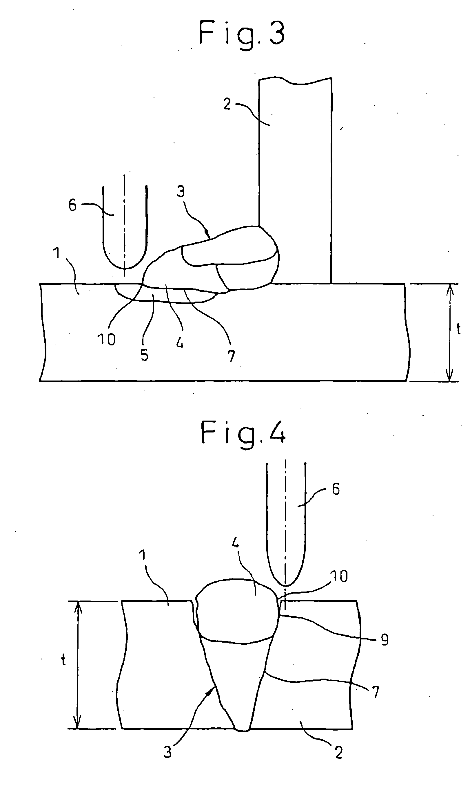
[0054] Steel plates having the compositions, plate thicknesses, and strengths shown in Table 1 were subjected to butt welding or fillet welding. The welding method was made any of SAW (Submerged Arc Welding), CO2 welding (CO2 Arc Welding), and MAG welding (Metal Arc Welding) as shown in Table 2. The crystal grain sizes of the HAZ microstructures (averages of longitudinal axis) formed by the last pass (pass adjacent to the toe in the case of the fillet welding) were measured, whereupon they all were 100 μm or more.

[0055] Next, in Example Nos. 1 to 7 of the present invention, when the ultrasonic impacts was carried out by an ultrasonic vibration tool having a pin diameter of 10 to 30 mm, all of the crystal grain sizes of the HAZ microstructures (averages of longitudinal axis) adjace...

third example

[0058] Steel plates having the compositions, plate thicknesses, and strengths shown in Table 3 were subjected to two-pass large heat input welding.

[0059] The steel plate compositions other than Example No. 25 and No. 30 shown in Table 3 were made chemical compositions suppressing the coarsening of the crystal grain size due to the welding heat input by the pinning effect obtained by dispersing fine oxides such as Ca, Mg, etc.

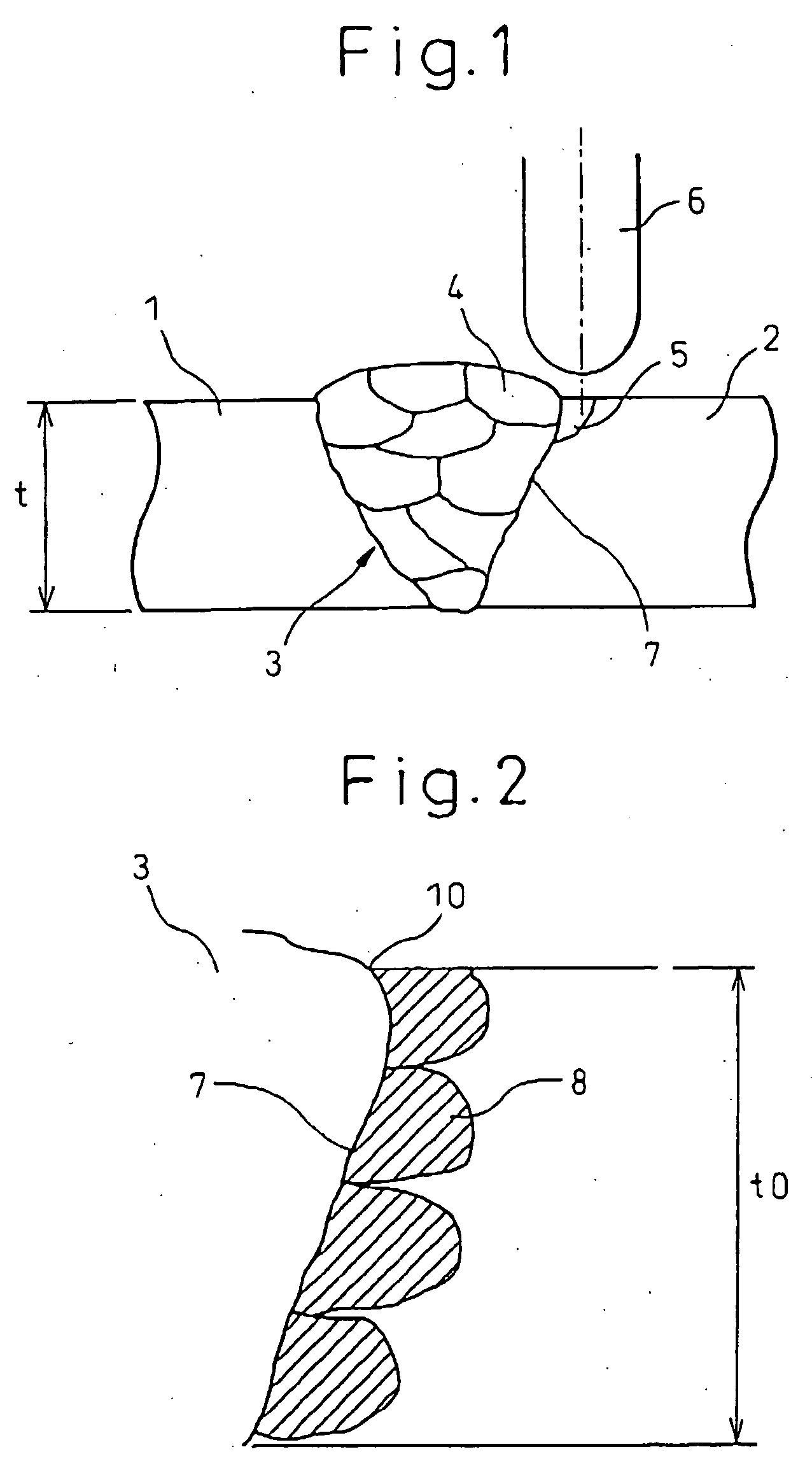
[0060] When the welding method was made large heat input welding methods able to perform large heat input welding of 90 kJ / cm such as° FAB (Flux Asbestos Backing) welding, VEGA welding (Vibrated Electro-Gas Arc Welding), and SEG-ARC welding (Sinko Electro-Gas-ARC Welding) as shown in Table 4, and the undercut lengths in the toes were measured, all were 0.5 mm or more.

[0061] Next, in Example No. 12 to No. 25 of the present invention, when ultrasonic impacts was carried out by an ultrasonic vibration tool having a pin diameter of φ10 to 30 mm, all undercut leng...


PUM

PropertyMeasurementUnit
diameteraaaaaaaaaa
diameteraaaaaaaaaa
crystal grain sizeaaaaaaaaaa

Abstract

A method of improvement of toughness of a heat affected zone in a multi-layer welded joint, a fillet welded joint, and a one-pass or several-pass large heat input welded joint of a steel plate is provided, that is, a method of improvement of toughness of a heat affected zone in a welded joint of a steel plate characterized subjecting a surface of a heat affected zone formed by a last pass of a multi-layer welded joint of a steel plate to impacts by an ultrasonic vibration tool or shot peening by ultrasonic vibration steel balls to thereby make an average of longitudinal axis of crystal grains up to a depth of 2 mm or more from the surface of the steel plate in the microstructure adjacent to a fusion line (FL) of a weld metal and a steel plate matrix in said heat affected zone formed by the last pass the equivalent of the crystal grain size of the steel plate matrix before the welding at a depth of ¼ of a thickness t from the surface of the steel plate.

Description

TECHNICAL FIELD [0001] The present invention relates to a method of improvement of toughness of a heat affected zone in a welded joint of a steel plate used for buildings, shipbuildings, bridges, construction machines, offshore structures, and other welded structures. Specifically, the present invention relates to a method of improvement of toughness of a heat affected zone in a multi-layer welded joint, a fillet welded joint, and a one-pass or several-pass large heat input welded joint. BACKGROUND ART [0002] In general, as the welded joints used for buildings, shipbuildings, bridges, construction machines, offshore structures, and other welded structures, there are the multi-layer welded joints obtained by welding by a large number of passes, the fillet welded joints for welding corners by perpendicularly arranging steel plates with each other, and the one-pass or several-pass welded joints obtained by large heat input welding. A detailed description will be given of the convention...

Claims


Application Information

Patent Timeline
Patent Type & Authority Applications(United States)
IPC IPC(8): C21D10/00B23K31/00B23K20/10B23K33/00C21D7/04C21D7/06C21D9/50
CPCB23K20/10B23K33/004B23K2203/04C21D7/04Y10T29/4583C21D9/50C21D10/00Y10T29/4578C21D7/06B23K2103/04
Inventor ISHIKAWA, TADASHINAKASHIMA, KIYOTAKANOSE, TETSURO
Owner NIPPON STEEL CORP
Why Eureka
Try Eureka