Position detecting apparatus having electric motor and method for detecting position

a technology of position detecting and electric motor, which is applied in the direction of motor control of motor oscillation damping, magnetic circuit, synchronous motor, etc., can solve the problems of increasing the output torque of the motor in dependence on the environment, deformation and breakage of components of the transmission system and the hooking portion, and the collision of components can cause the load to be reduced, and the mechanical damage of the components can be reduced

Active Publication Date: 2006-06-29
DENSO CORP +1
View PDF6 Cites 36 Cited by
  • Summary
  • Abstract
  • Description
  • Claims
  • Application Information

AI Technical Summary

Benefits of technology

[0008] In view of the foregoing and other problems, it is an object of the present invention to produce a position detecting apparatus, the apparatus being capable of reducing damage occurring in a detecting operation of the position. It is another object of the present invention to produce a method for detecting the position in an object.
[0016] In the above structure, a load caused by collision of components can be reduced. Therefore, mechanical damage in the components can be reduced.

Problems solved by technology

When the tapping control is performed, the following problems may arise.
First, when a movable member collides against a fixed member in the tapping control, a mechanical load is applied to both the movable member and the fixed member.
Accordingly, as the number of the tapping control increases, mechanical damage may occur in the components of the transmission system and in the hooking portion, in which the movable member hooks to the fixed member.
As a result, the components of the transmission system and the hooking portion may be gradually deformed and broken.
Specifically, the output torque of the motor may increase in dependence upon the environment and the operating condition.
In this situation, mechanical load may increase when the movable member collides against the fixed member.
Accordingly, as the number of the tapping control increases, the number of applying large load torque increases, and as a result, mechanical damage may occur in the components of the transmission system and the hooking portion.
In addition, the components are not necessarily perfect rigid bodies.
That is, the components are macroscopically spring elements, and the components may cause deflection when being applied with force.
As a result, the reference position, which is learned during the tapping control of the movable member, cannot be stable.
Thus, a positioning control of the movable member cannot be steadily performed.
Third, as the rotation speed of the electric motor increases, the output torque of the electric motor decreases.
Consequently, large mechanical torque is applied to the components of the transmission system and the hooking portion between the movable member and the fixed member.
Consequently, mechanical damage may occur in the components of the transmission system and the hooking portion.

Method used


Image

  • Position detecting apparatus having electric motor and method for detecting position
  • Position detecting apparatus having electric motor and method for detecting position
  • Position detecting apparatus having electric motor and method for detecting position

Examples


first embodiment

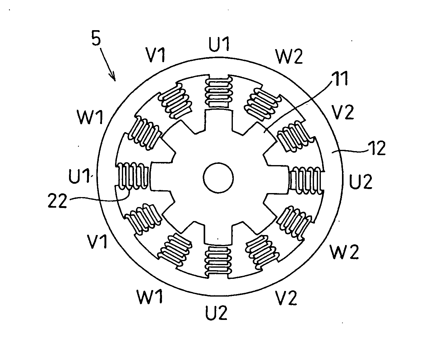
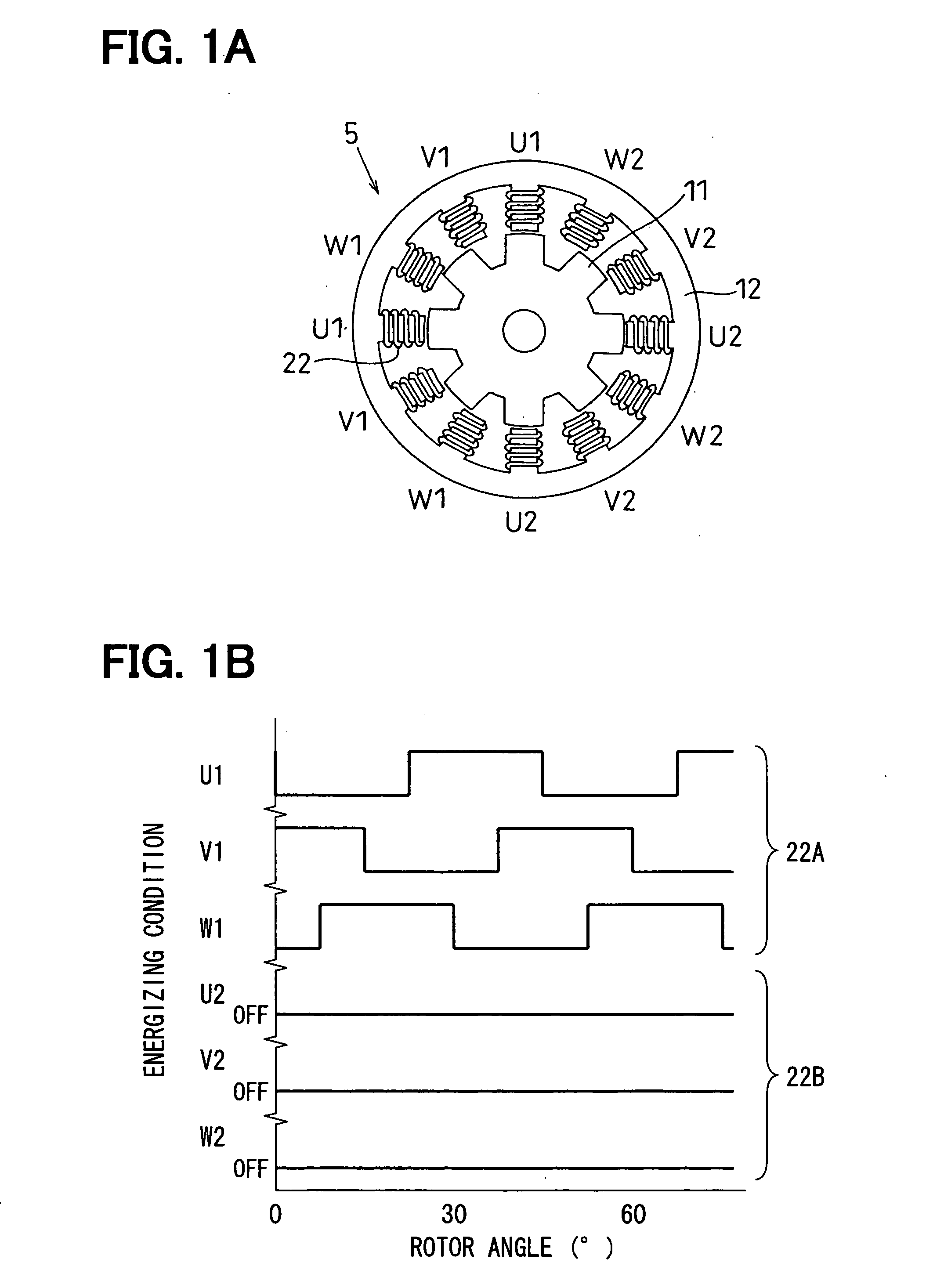
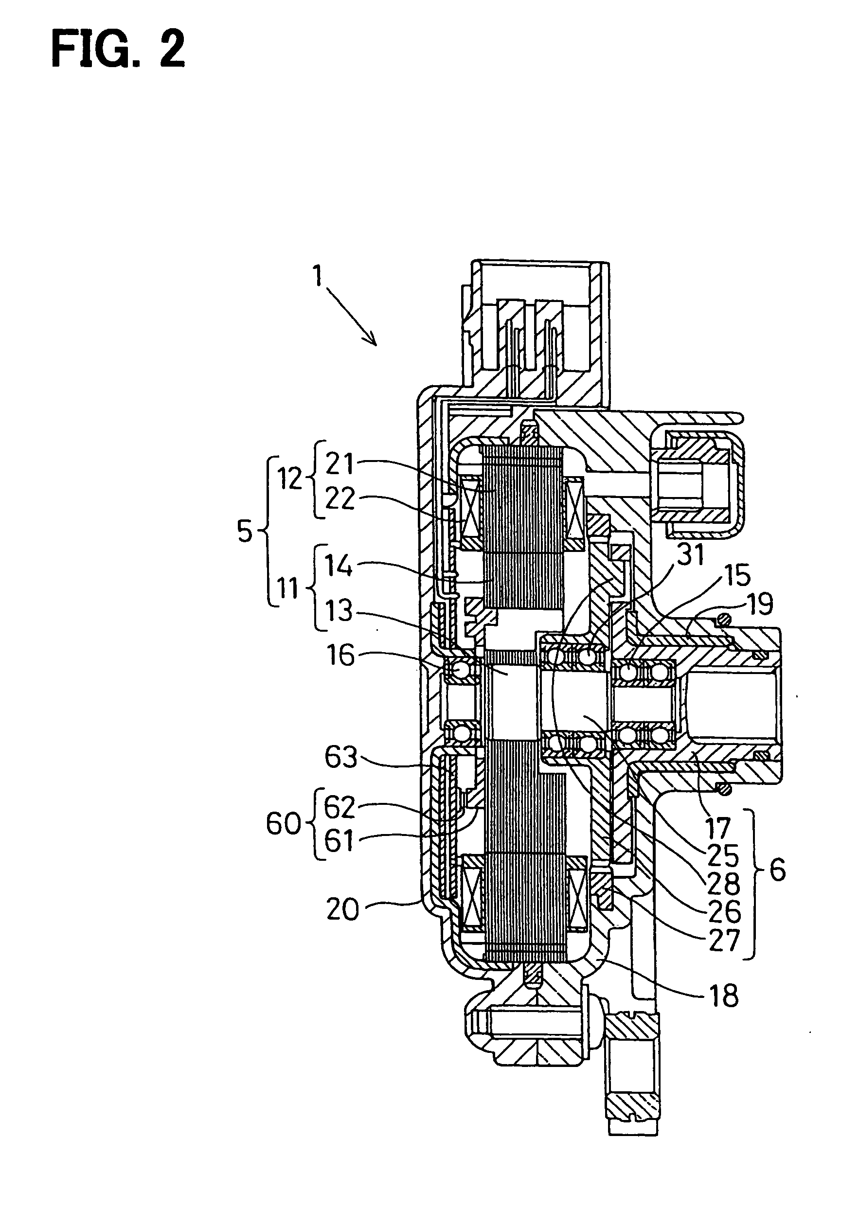
[0035] As shown in FIGS. 1A to 3, a shift range switching apparatus includes a rotative actuator 1 (FIG. 2) that switches a shift range switching device 3, which includes a parking switching device 4 (FIG. 4). The shift range switching device 3 is an example of a driven object. The shift range switching device 3 is provided to an automatic transmission 2 of a vehicle. The rotative actuator 1 is a servo device that operates the shift range switching device 3. The rotative actuator 1 includes a synchronous electric motor 5 and a reduction gear (reduction unit) 6. The reduction gears 6 reduce rotation speed of the electric motor 5. The electric motor 5 is controlled using an ECU (electronic control unit) 7. The ECU 7 serves as a motor control unit.

[0036] Specifically, the ECU 7 controls the rotative direction of the electric motor 5, the rotation speed (number of rotation) of the electric motor 5, and rotation angle of the electric motor 5 in the shift range switching apparatus, there...

second embodiment

[0117] The characteristic of the battery (power source), which supplies electricity to the electric motor 5, may vary in dependence upon the environment of the battery. Specifically, output voltage of the battery and a performance for supplying electricity to the electric motor 5 may vary in dependence upon the environment such as the season. In particular, the variation in the characteristic of the battery is apt to be large in summer and winter. In these cases, output torque of the electric motor 5 may vary due to the variation in output voltage of the power source and the variation in the capacity of the power source for supplying electricity.

[0118] Furthermore, the components are not completely rigid members, and may be deformed by applying force. That is, the components are macroscopically spring elements. Accordingly, when the output torque of the electric motor 5 varies, an amount of deformation arising in the components in the tapping control may vary. As a result, the refe...

third embodiment

[0132] As the rotation speed of the electric motor 5 increases, the output torque of the electric motor 5 is apt to decrease. By contrast, as the rotation speed of the electric motor 5 decreases, the output torque of the electric motor 5 is apt to increase. Therefore, the electric motor 5 generates substantially the maximum torque when the electric motor 5 stops. That is, when the hooking portion 47a of the detent spring 47 collides against the restriction wall of the detent plate 46, and the electric motor 5 stops during the tapping control, the electric motor 5 generates substantially the maximum torque.

[0133] Accordingly, as the number of the tapping control increases, mechanical damage may occur in the components of transmission system and in the hooking portion. As a result, the components of the transmission system and the hooking portion may be gradually deformed and broken.

[0134] Furthermore, the components are not completely rigid, and may macroscopically be spring elemen...


PUM


Abstract

A reference position detecting apparatus includes an electric motor and a motor control unit. The electric motor includes a plurality of first coils and a plurality of second coils. The electric motor further includes a rotor that rotates when at least one of the plurality of first coils and the plurality of second coils is supplied with electricity. The motor control unit controls electricity supplied to either one of the plurality of first coils and the plurality of second coils to rotate the rotor to a limit position in a movable range of an object.

Description

CROSS REFERENCE TO RELATED APPLICATIONS [0001] This application is based on and incorporates herein by reference Japanese Patent Applications No. 2004-381753 filed on Dec. 28, 2004. FIELD OF THE INVENTION [0002] The present invention relates to a position detecting apparatus having an electric motor. In particular, the present invention relates to an apparatus for detecting a reference position of a driven object to define an initial position of the driven object in a starting condition of a vehicle. Specifically, the present invention relates to a technology for defining an initial position of one of a rotor and a shift range switching device using an electric motor in an automatic transmission apparatus for a vehicle, for example. In addition, the present invention relates to a method for detecting a position in an object. BACKGROUND OF THE INVENTION [0003] According to JP-A-2004-12299 (U.S. Pat. No. 6,911,798 B2), an electric motor operates a shift range switching device for an a...

Claims


Application Information

Patent Timeline
Patent Type & Authority Applications(United States)
IPC IPC(8): H02K11/00H02K3/00G01R33/10F16H61/32H02K19/10H02K21/16H02P21/05H02P21/36H02P23/04H02P25/08H02P25/098H02P27/06
CPCF02D41/009F02D2041/0092F02N11/0859F02N19/005Y10T74/19251F02P7/067H02K11/0021H02P1/02F02P7/061H02K11/215
Inventor KIMURA, KIYOSHIITOH, TAKUYOSHIYAMA, SHIGERUHORI, MASASHI
Owner DENSO CORP
Why Eureka
Try Eureka