Phase locked loop
- Summary
- Abstract
- Description
- Claims
- Application Information
AI Technical Summary
Benefits of technology
Problems solved by technology
Method used
Image
Examples
Embodiment Construction
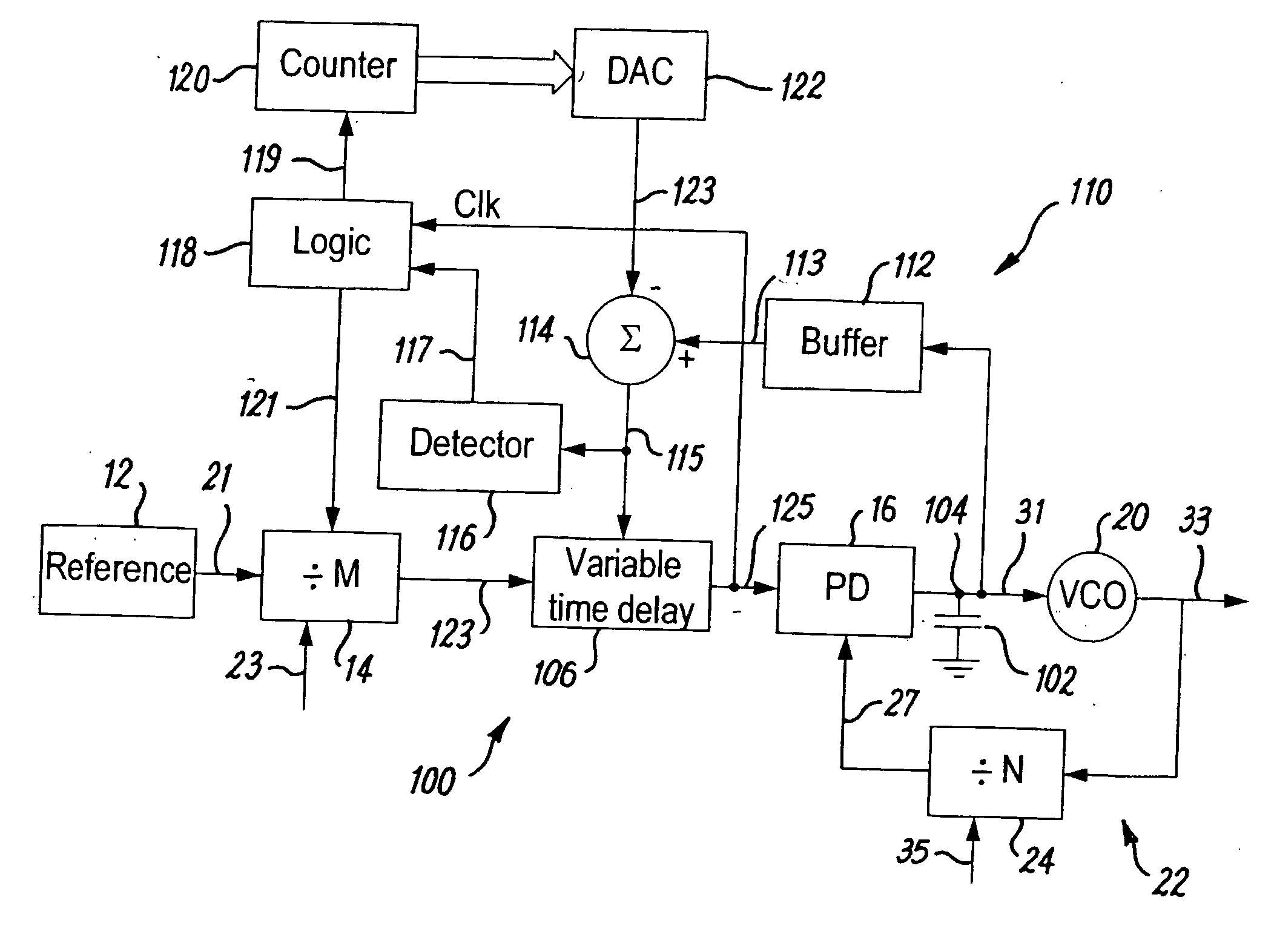
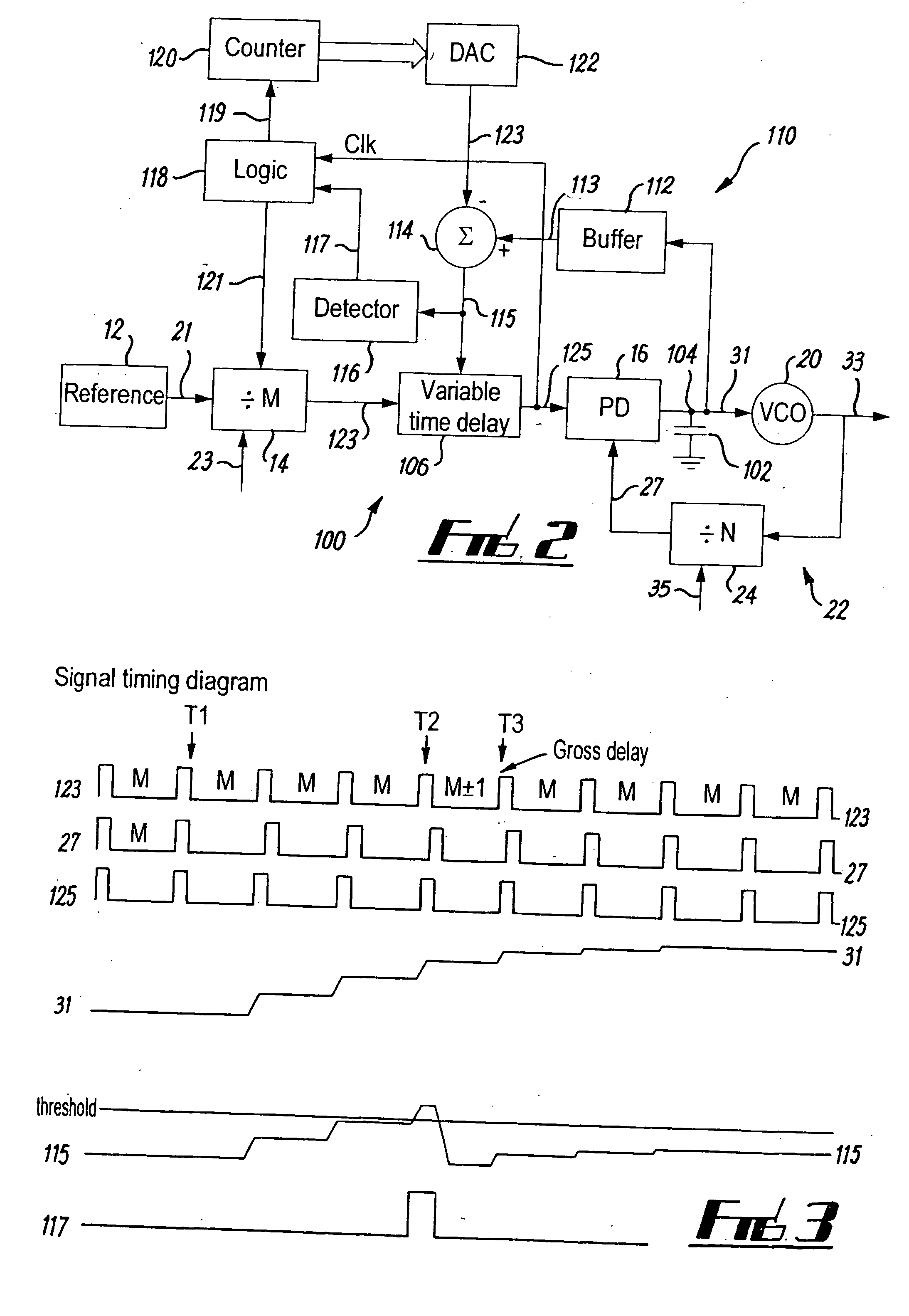
[0027]FIG. 2 illustrates an adapted phase locked loop (PLL) 100 with a delay locked loop (DLL) wrapped around the phase detector 16.
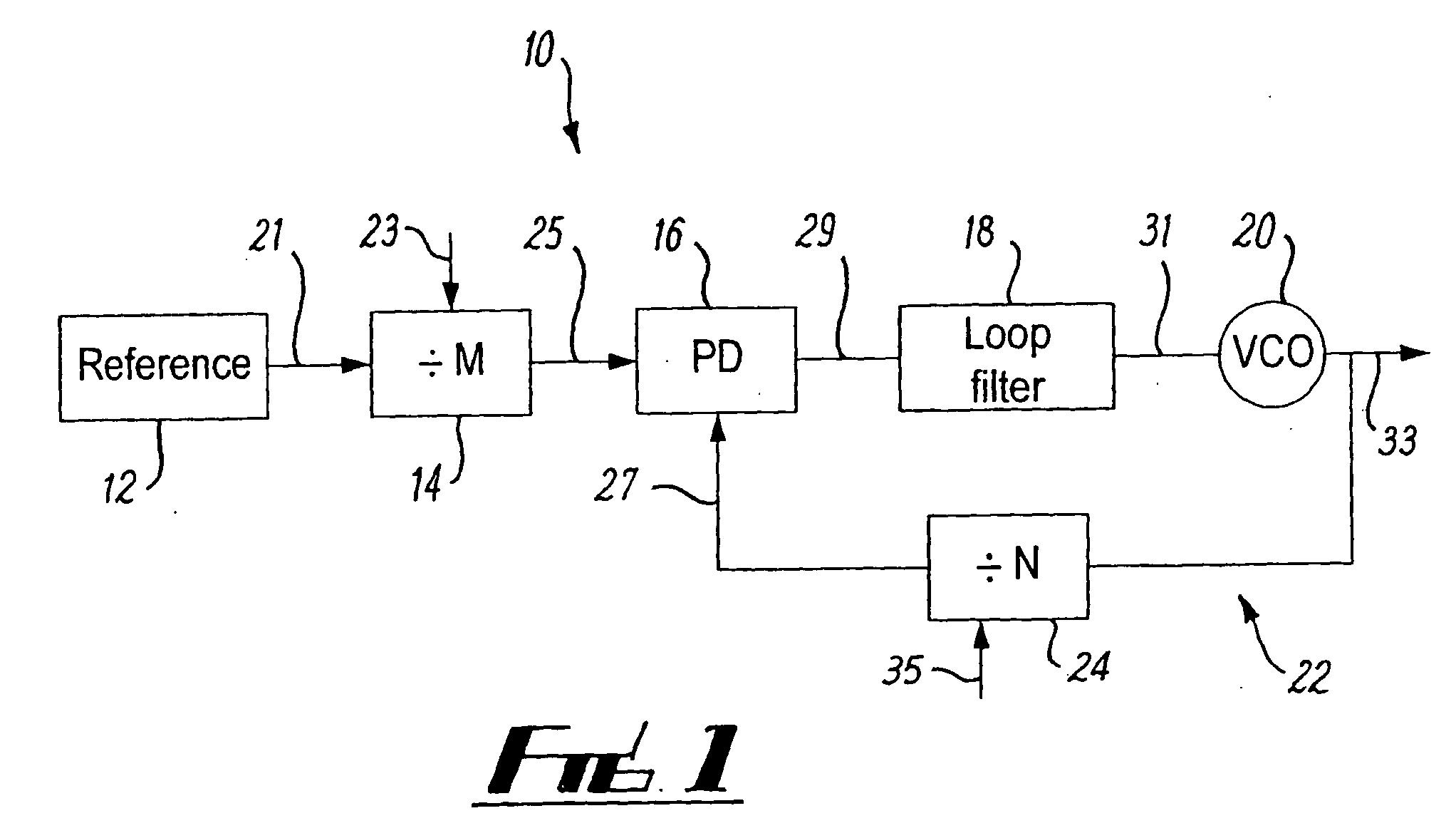
[0028] The adapted PLL 100 differs from the PLL 10 of FIG. 1 in that:
a) the multi-component loop filter has been replaced by a simplified loop filter, which in this example comprises a single capacitor 102 connected between a node 104, between the phase detector 16 and the VCO 20, and ground.
b) it additionally has a variable delay component 106 connected between the first counter 14 and the phase detector 16
[0029] c) it has a feedback path from the phase detector 16 back to the variable delay component 106 and the reference counter 14 so as to form a delay locked loop (DLL) 110 wrapped around the phase detector 16. The feedback path takes as an input the output of the phase detector 16, and provides a first delay control signal 121 to the reference counter 14 and provides a second delay control signal 115 to the variable delay component 106.
[0030]...
PUM
 Abstract
Description
Claims
Application Information
 - R&D
- Intellectual Property
- Life Sciences
- Materials
- Tech Scout
- Unparalleled Data Quality
- Higher Quality Content
- 60% Fewer Hallucinations
Browse by: Latest US Patents, China's latest patents, Technical Efficacy Thesaurus, Application Domain, Technology Topic, Popular Technical Reports.
© 2025 PatSnap. All rights reserved.Legal|Privacy policy|Modern Slavery Act Transparency Statement|Sitemap|About US| Contact US: help@patsnap.com


