Multi-channel dpsk receiver

a receiver and multi-channel technology, applied in multiplex communication, wavelength-division multiplex systems, instruments, etc., can solve the problems of increasing size, weight, power, cost, etc., and achieves cost reduction, wideband dpsk, and significant cost reduction.

Active Publication Date: 2006-06-29
MASSACHUSETTS INST OF TECH
View PDF5 Cites 21 Cited by
  • Summary
  • Abstract
  • Description
  • Claims
  • Application Information

AI Technical Summary

Benefits of technology

[0005] An optical, multi-channel, Differential Phase Shift Keying (DPSK) receiver, and corresponding method, employing the principles of the present invention demodulates multiple Wavelength Division Multiplexed (WDM) channels using a single interferometer. A DPSK receiver using a single interferometer for WDM demultiplexing is achieved by constraining the received wavelength spacing (Δνch) and leveraging the interferometer's periodic transfer function to perform demodulation on all channels (λ's). This distributes the expense of the interferometer over all channels, allowing for deployment of cost-effective, scalable, wideband, WDM DPSK systems. For example, for an 80 channel receiver, size, weight, and power (SWAP), and costs are significantly reduced through use of a single interferometer instead of eighty interferometers and associated stabilization electronics. The receiver is architecturally compatible with existing interferometer technologies, so previous development and qualification efforts can be leveraged. Such leveraging allows for expedited technology insertion into existing optical communications networks, including terrestrial and space-based optical networks.
[0009] The interferometer may also be adapted to demodulate optical signals having wavelength spacing between carrier wavelengths defining the channels evenly divisible by an odd number of half channel rates of the optical signal. For example, 40 Gbps goes into 100 GHz channel spacing exactly 2 ½ times. The received Signal-to-Noise Ratio (SNR) remains intact, but the received data is inverted—a condition that can be anticipated or detected and corrected via post processing. In one embodiment, detection electronics perform the post processing by correcting polarity of electrical signals of received optical channels as necessary, which may correspond to predefined optical channels. In another embodiment, optical elements perform the post processing by correcting polarity of the phase demodulated optical signal. With this capability, a multi-wavelength DPSK receiver can receive all channels without any penalty whenever the channel spacing is evenly divisible by the half channel rate.
[0010] For prior art, single channel, DPSK receivers, the interferometer may track on the single carrier wavelength to optimize demodulator performance and compensate for transmitter or interferometer drift. However, for multiple-channel reception with a single interferometer, the interferometer can only adjust the period (i.e., wavelength or channel separation) and / or shift the entire comb of channels. Thus, a single interferometer cannot track and lock onto arbitrarily spaced wavelengths simultaneously in order to optimize performance. Therefore, the optical receiver according to the principles of the present invention may also include a feedback processor that generates signals transmitted to transmitter(s) of the optical signal(s) to cause the transmitter(s) to tune carrier wavelengths defining the channels. Tuning the carrier wavelengths allows for independent channel adjustment and alignment to the interferometer for improved demodulation performance. With this feedback, independent transmitter wavelengths can be precisely aligned to the interferometer, despite potential drift in the transmitter wavelengths relative to the interferometer. Such feedback, for example, could be used to compensate for laser aging or for Doppler shifts.
[0012] To support interferometer control, the interferometer may receive a pilot signal or plurality of pilot signals that serve(s) as reference wavelengths that the interferometer can lock-on to for stabilization and / or alignment to incoming optical signal(s). The pilot signal(s) may be locally resident or distributed, may be tunable, and may be selected to be outside the standard communications band so as not to impact the available communications spectrum. As an example, the pilot tone to which the interferometer locks-on can be a dominant incoming channel that may be selectable by the network. With feedback, the interferometer and all other channels including locally resident references can be spaced at wavelengths relative to the dominant signal. In the event the dominant channel drops out, locally resident pilot tone(s) or other incoming channels, which have been aligned relative to the dominant channel can take over as the reference, allowing for continued wavelength alignment and control. The use of multiple pilot tones can be used to improve interferometer control and provide a means of measuring interferometer parameters, such as Free Spectral Range (FSR).

Problems solved by technology

Of these elements, the interferometer is the most technically challenging and the least mature.
As a result, carefully designed thermo-mechanical packaging is necessary in addition to stabilization electronics, adding to size, weight, power, and cost.

Method used


Image

  • Multi-channel dpsk receiver
  • Multi-channel dpsk receiver
  • Multi-channel dpsk receiver

Examples


Embodiment Construction

[0024] A description of preferred embodiments of the invention follows.

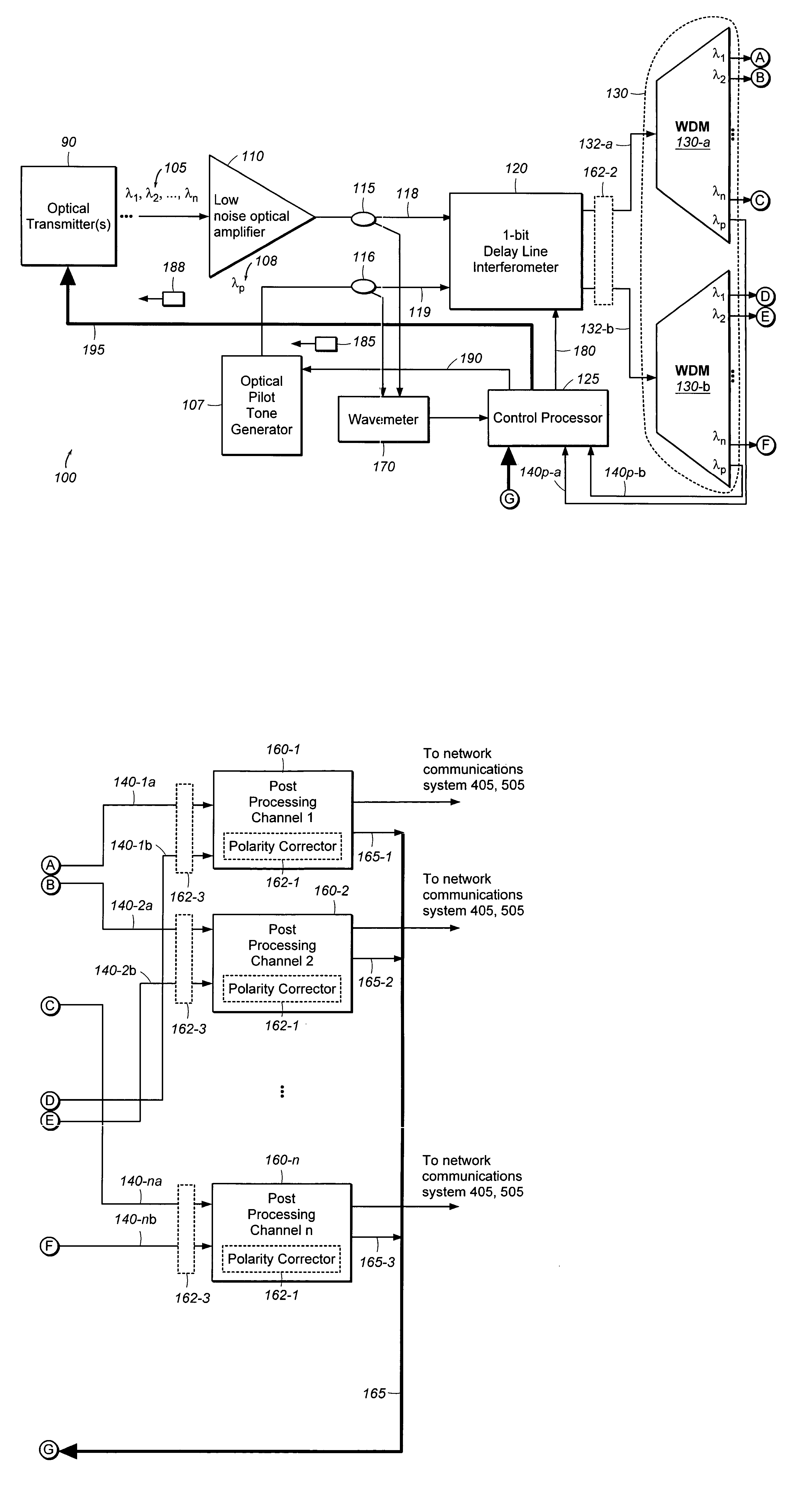
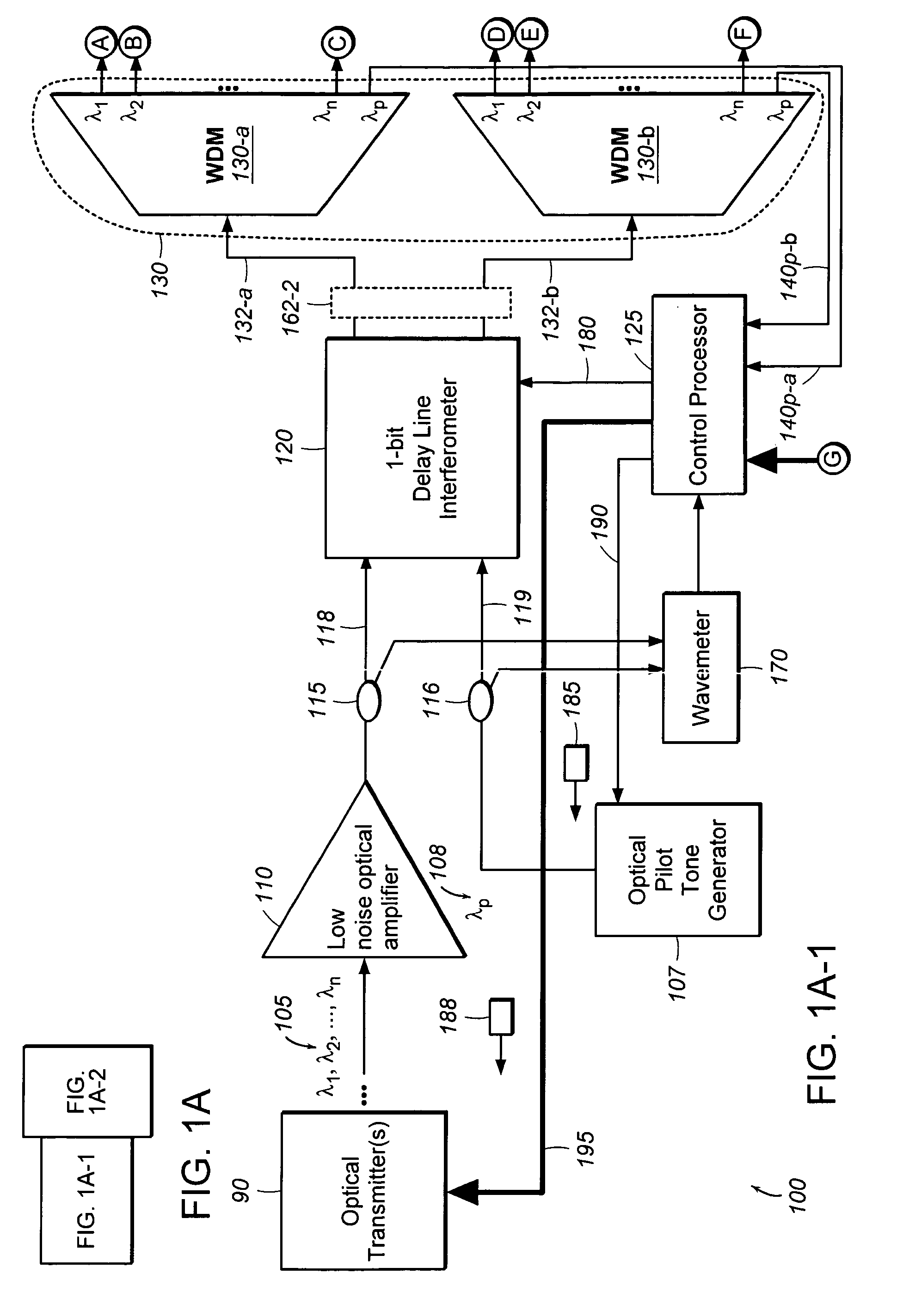
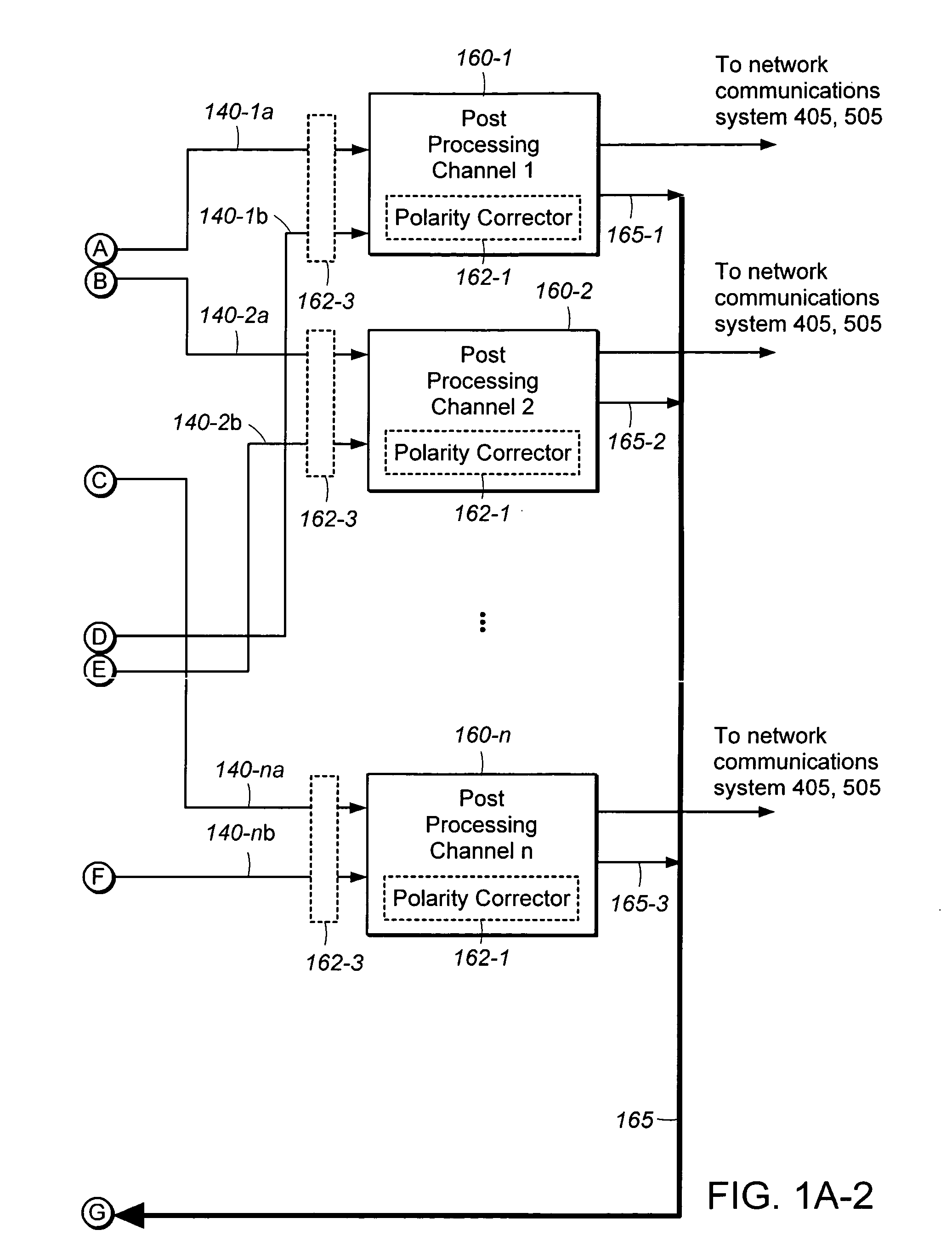
[0025]FIG. 1A and FIG. 1B are schematic diagrams of example embodiments of an optical, multi-channel, DPSK receiver 100 according to the principles of the present invention. The receiver 100 receives optical signal(s) 105 from optical transmitter(s) 90. The optical signal(s) 105 may have many DPSK channels defined by distinct wavelengths, λ1, λ2, . . . , λn. In one embodiment, the optical signal(s) 105 are received by an optical amplifier 110, such as a low noise Erbium Doped Fiber Amplifier (EDFA) 110, that may be separate from the receiver 100 or integrated into the receiver 100. The EDFA 110 outputs amplified optical signal(s) 105 to a first optical splitter 115, which directs a portion of the amplified optical signal(s) 105 to an interferometer 120, such as a 1-bit delay line interferometer 120, via a primary input line 118. The delay line interferometer 120 is sometimes referred to as a “delay and multiply ...


PUM

PropertyMeasurementUnit
wavelength rangesaaaaaaaaaa
optical center frequenciesaaaaaaaaaa

Abstract

An optical, multi-channel, Differential Phase Shift Keying (DPSK) receiver demodulates multiple Wavelength Division Multiplexed (WDM) channels using a single interferometer. This distributes expense of the interferometer over all channels of an optical signal, allowing for deployment of cost-effective, scalable, wideband, WDM DPSK systems. For example, for an 80 channel WDM link, the receiver uses a single interferometer instead of eighty interferometers and associated stabilization hardware, dramatically reducing size, weight, power, and cost. The receiver is architecturally compatible with existing interferometer technologies so previous development and qualification efforts can be leveraged. This allows for expedited technology insertion into existing optical communications networks, including terrestrial and space-based optical networks.

Description

RELATED APPLICATION(S) [0001] This application claims the benefit of U.S. Provisional Application, “Polarization Independent Interferometers”, Attorney docket number 0050.2071-000, filed concurrently herewith. The entire teachings of the above application(s) are incorporated herein by reference.GOVERNMENT SUPPORT [0002] The invention was supported, in whole or in part, by a grant under Contract No. F19628-00-C-0002 from the United States Air Force. The Government has certain rights in the invention.BACKGROUND OF THE INVENTION [0003] Recently, optical Differential Phase Shift Keying (DPSK) modulation has received considerable attention by the telecommunications industry primarily due to its increased sensitivity over commonly used On-Off-Keying (OOK) and its reduced peak power, which mitigates nonlinear effects in fiber-optic applications. This has led to demonstrated utility in long haul applications, with experiments confirming more than 3 Tb / s capacity using 80 Wavelength Division...

Claims


Application Information

Patent Timeline
Patent Type & Authority Applications(United States)
IPC IPC(8): G02F2/00
CPCH04B10/67H04B10/677H04B10/69H04J14/02
Inventor CAPLAN, DAVID O.
Owner MASSACHUSETTS INST OF TECH
Why Eureka
Try Eureka