
Plant temperature control system

Inactive Publication Date: 2006-06-29
HONDA MOTOR CO LTD
View PDF6 Cites 18 Cited by
  • Summary
  • Abstract
  • Description
  • Claims
  • Application Information

AI Technical Summary

Benefits of technology

[0006] An object of this invention is therefore to overcome the foregoing drawback by providing a plant temperature control system that accurately corrects the temperature estimated value produced by the plant model even when the response delay of the temperature sensor is large.
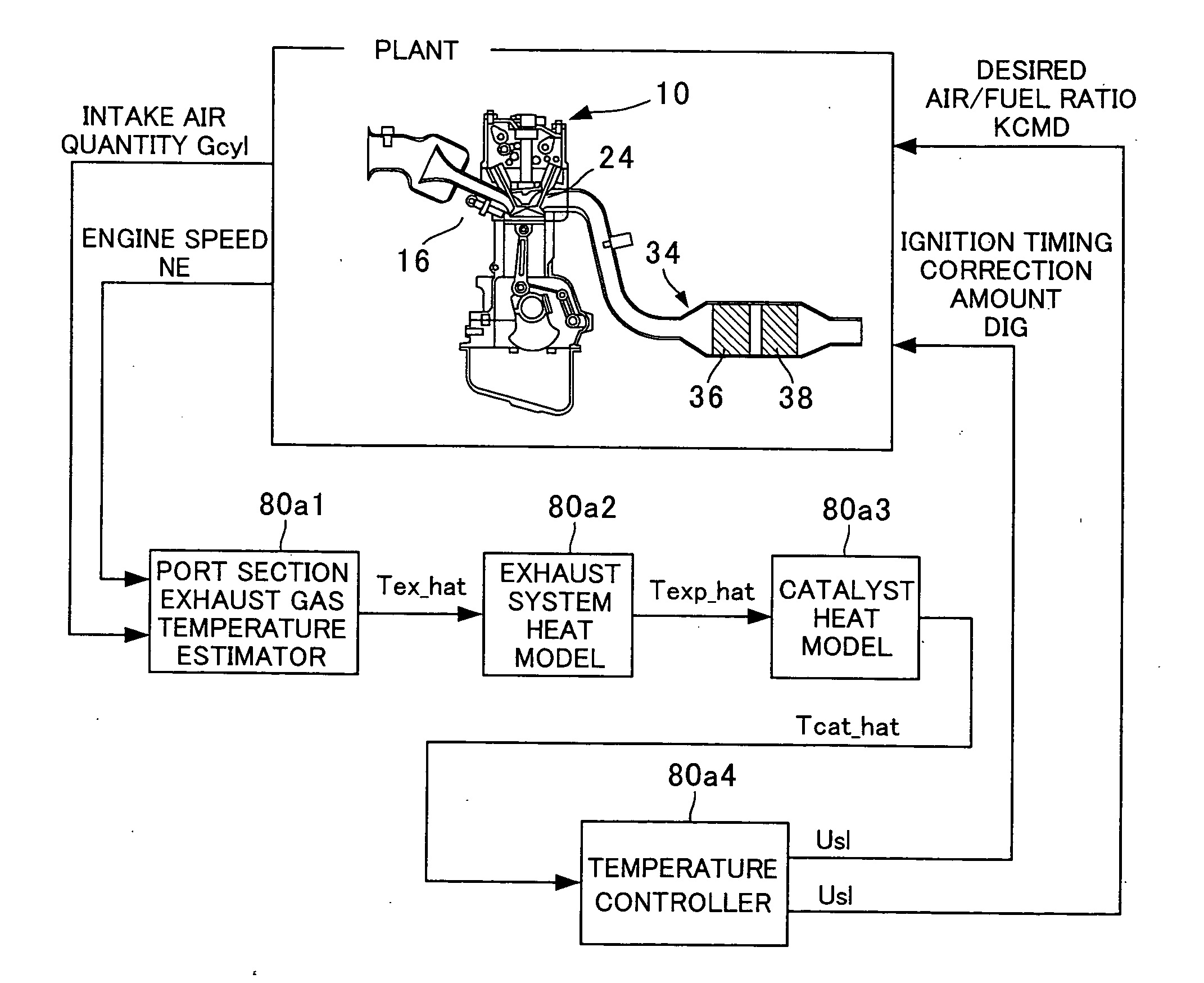
[0007] In order to achieve the object, this invention provides a system for controlling temperature of a plant, comprising: a temperature sensor producing an output indicative of a temperature of the plant; a plant model calculating a temperature estimated value of the plant; a temperature sensor model inputting the calculated temperature estimated value of the plant and calculating an output estimated value of the temperature sensor; a temperature controller controlling the temperature of the plant based on the calculated temperature estimated value of the plant; and a model parameter corrector correcting a parameter of the plant model so as to minimize error between the output of the temperature sensor and the calculated output estimated value of the temperature sensor.

Problems solved by technology

However, the response of a temperature sensor that can bear up under the temperature fluctuation range of a vehicle exhaust system is usually very poor.
Therefore, when the temperature estimated value of the plant model is corrected immediately using the output of the temperature sensor as described in the prior art, a miscorrection is liable to be made.

Method used


Image

  • Plant temperature control system
  • Plant temperature control system
  • Plant temperature control system

Examples


first embodiment

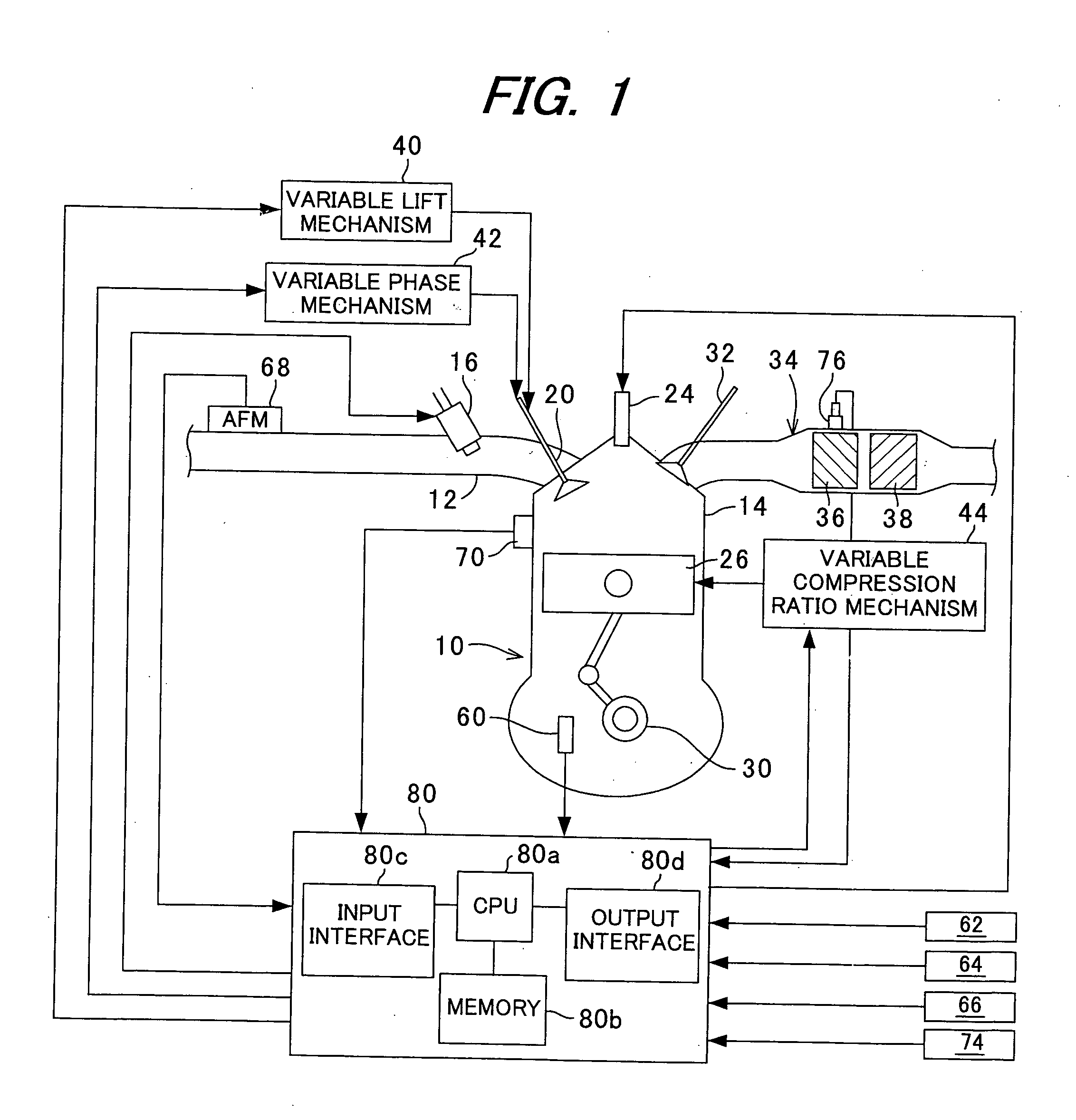
[0138] As explained in the foregoing, the plant temperature control system is equipped with the temperature sensor 76 for producing an output indicative of the temperature Tcat of the exhaust system (plant) 34, the catalyst (CAT) heat model (plant model) 80a3 for calculating the temperature estimated value Tcat_hat of the plant, the temperature sensor model 80a5 responsive to input of the calculated plant temperature estimated value for calculating the output estimated value Tcat_sm of the temperature sensor, and the temperature controller 80a4 for controlling the plant temperature based on the calculated plant temperature estimated value, and is further equipped with the model parameter corrector 80a6 for correcting the parameter of the plant model so as to minimize error Eest between the temperature sensor output Tcat and the calculated output estimated value Tcat_sm. Owing to this configuration, even in the case where the temperature sensor 76 has a large response lag, the tempe...

second embodiment

[0140]FIG. 21 is a block diagram similar to that of FIG. 13 showing the configuration of a plant temperature control system according to the invention.

[0141] The catalyst heat model 80a3 of the plant temperature control system according to the first embodiment is corrected for all temperature estimation-related errors by the correction term Dcat. However, the Tcat_hat estimation error is produced chiefly by aging of the first and second catalytic converters 36 and 38 and change in the reaction heat of the NOx catalyst converter 36 caused by, for example, change in the unburned gas properties.

[0142] In response to this point, the heat model parameter Ccat of the catalyst heat model 80a3 in the plant temperature control system according to the second embodiment is, as shown in FIG. 21, replaced with one sequentially calculated by the model corrector 80a6 and the model corrector 80a6 is modified as shown.

[0143] In the second embodiment, the catalyst heat model 80a3 is represented by ...

third embodiment

[0146]FIG. 22 is a block diagram similar to that of FIG. 13 showing the configuration of a plant temperature control system according to the invention.

[0147] In the second embodiment shown in FIG. 21, the heat model parameter Ccat of the catalyst heat model 80a3, which parameter is the chief cause of error in the estimation of Tcat_hat, is sequentially calculated by the model corrector 80a6. The plant temperature control system according to the third embodiment is configured to make concurrent use of the model correction term Dcat utilized in the control system of the first embodiment shown in FIG. 13.

[0148] In the third embodiment, the catalyst heat model 80a3 is represented by the following equations. Tcat_hat⁢(k)-Tcat_hat⁢(k-1)Δ⁢ ⁢T=Acat⁡(Tcat_hat⁢(k-1)-TA⁡(k-1))-Bcat⁢ ⁢Gcyl⁡(k-1)Lcat⁢ ⁢Gcyl_max⁢(Texp_hat⁢(k-1)-Tcat_hat⁢(k-1))+Ccat⁡(k-1)⁢Gcyl⁡(k-1)+Dcat⁡(k-1)⁢⇓(3⁢-⁢5)Tcat_hat⁢(k)=(Acat⁢ ⁢Δ⁢ ⁢T+1+Bcat⁢ ⁢Gcyl⁡(k-1)⁢Δ⁢ ⁢TLcat⁢ ⁢Gcyl_max)⁢Tcat_hat⁢(k-1)-Bcat⁢ ⁢Gcyl⁡(k-1)Lcat⁢ ⁢Gcyl...


PUM


Abstract

In a temperature control system of a plant such as an engine exhaust system, there are provided a catalyst heat model calculating a temperature estimated value of the plant, a temperature sensor model inputting the calculated value to calculate an output estimated value of a temperature sensor, a temperature controller controlling the plant temperature based on the estimated value, and a model parameter corrector correcting the plant model parameter so as to minimize error between the temperature sensor output and the calculated output estimated value. With this, even in the case where the temperature sensor has a large response lag, the temperature estimated value can nevertheless be corrected with high accuracy, without, for example, causing severe overshooting.

Description

BACKGROUND OF THE INVENTION [0001] 1. Field of the Invention [0002] This invention relates to a plant temperature control system. [0003] 2. Description of the Related Art [0004] As taught by WO 2002 / 070873, for example, the temperature control of a catalytic converter (viewed as a plant) of an internal combustion engine can be achieved by defining a plant model for estimating the temperature of the catalytic converter and detecting catalytic converter deterioration by comparing the model output with the output of a temperature sensor installed in the catalytic converter. When the sensor output indicates a temperature lower than the light-off temperature of the catalytic converter, the conventional system uses the temperature sensor output to correct the temperature estimated by the model and controls the fuel quantity and ignition timing of the engine so as to maintain reduced catalyst temperature so long as deterioration of the catalytic converter continues to be observed. [0005] H...

Claims


Application Information

Patent Timeline
IPC IPC(8): F01N11/00G05B13/04
CPCF01L1/352F01L13/0063F01L2001/0537F01N3/28F01N2570/10F01N2570/14F02D13/0219F02D13/0226F02D15/02F02D41/024F02D41/1402F02D41/1403F02D41/1446F02D2041/1433F02D2200/0802F02D2200/0804G01K7/42G01K2205/04H01M10/486H01M10/5004H01M10/5016H01M10/5022H01M10/5061Y02T10/26Y02T10/18F01N13/0097H01M10/625H01M10/633H01M10/613H01M10/656Y02T10/12Y02E60/10
Inventor YASUI, YUJI
Owner HONDA MOTOR CO LTD
Learn More