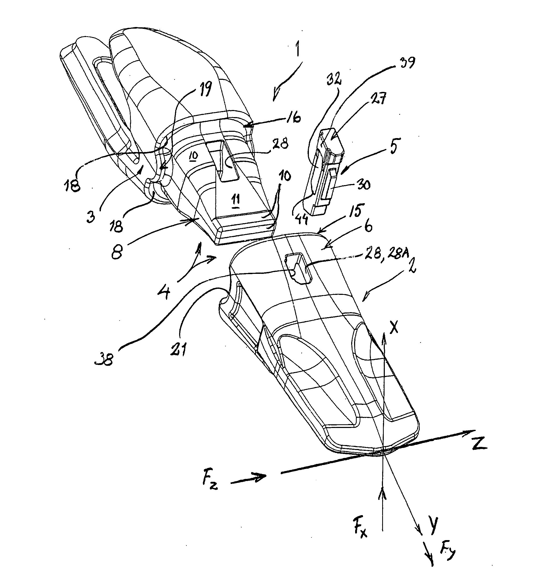
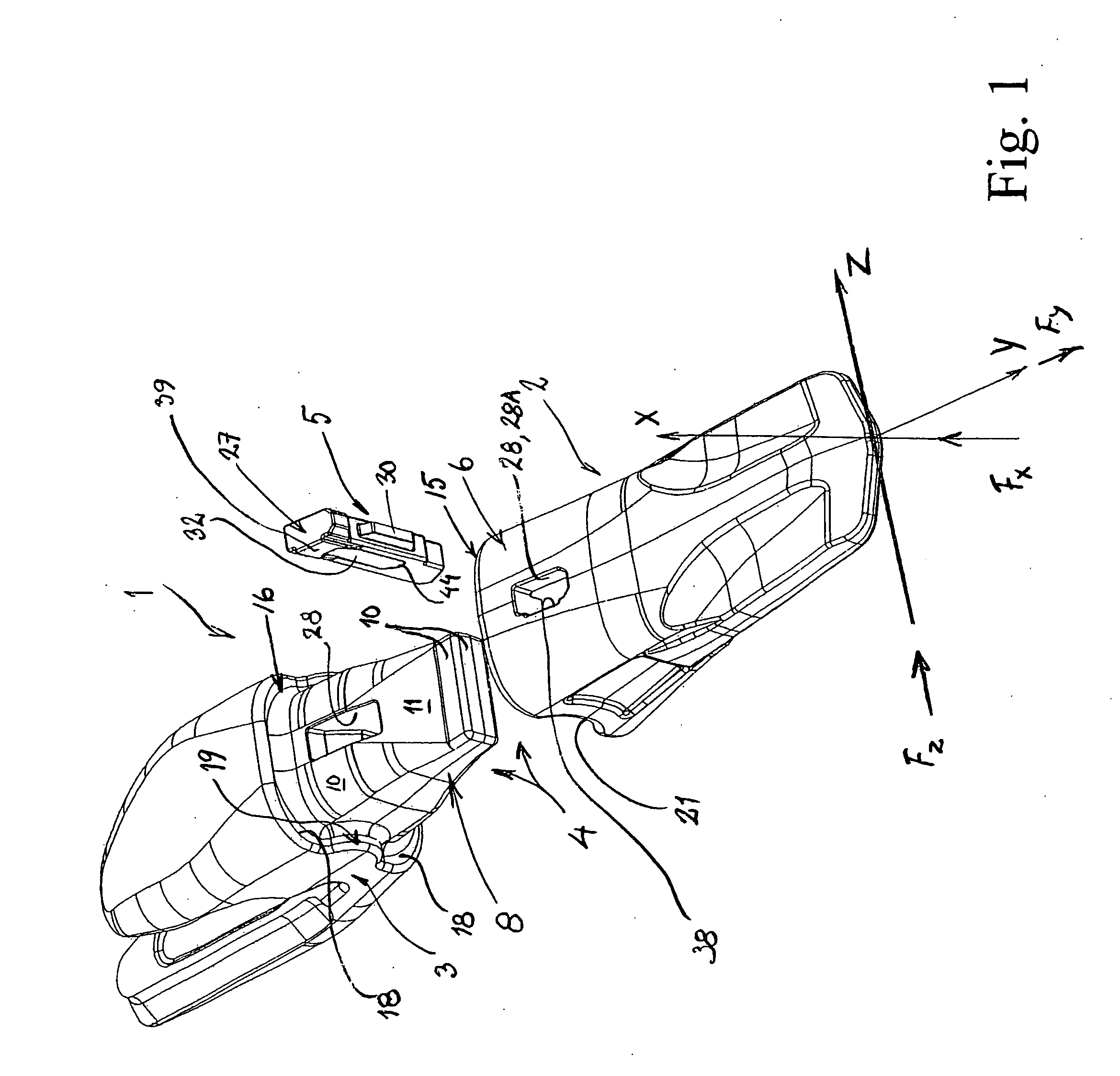
The component forces Fx, Fy and Fz can also, as a result of their leverage ratio, give rise to troublesome torque loads, which have to be absorbed via double contact zones disposed on either side of the axis about which the rotation occurs.
These projections and recesses respectively are herein meant to eliminate the mobility between the holder part and the
tine part which is a consequence of inevitable production tolerances, but they will also absorb torque loads, which can lead to the emergence of undesirable leverage ratios after a certain period of asymmetrical wear.
Moreover, both the
tine part and the holder part will suffer essentially equal wear, with the result that both of them have to be replaced once the wear has reached its
maximum level.
This is very costly, of course, and since each holder part, moreover, is welded to the bucket, the down time is far longer than with a rapid replacement of just the wearing part.
A further and very serious problem with the abovementioned
coupling systems is that the locking device risks being
cut off by the shearing forces which are generated, on the one hand, when the
tine part and the holder part are displaced horizontally toward each other owing to continuous wearing down of the angled stop faces and of the stop faces on the collars, and, on the other hand, when the
coupling system is subjected to unfavourable rotational loads about an unforeseen contact, newly arisen because of the wear, between the collars of the wearing parts system.
As the wear increases on the original vertical stop faces designed for wear, a second and undesirable secondary
contact zone will form, however, between the rear edge of the tine collar of the wearing part and the
front edge of the collar of the holder, i.e. a secondary stop zone is formed around the tine collar and the holder collar in the
vertical plane XZ of the respective collar, which edges / vertical planes do not initially meet and which secondary stop zone, moreover, will gradually grow.
A torque leverage which is very detrimental to the strength will in this case be obtained for the majority of load cases, which leverage will give rise to the shearing forces which will
cut off the locking device.
In the
coupling system according to U.S. Pat. No. 2,689,419, the locking wedge is at its weakest at the tapered end of the locking wedge, precisely where the said shearing forces are likely to be greatest, i.e. on the friction surfaces between the wearing part and the holder part, both owing to the leverage ratios of the said loads and owing to the fact that the play between the collars is equally great all the way round, with the result that the undesirable secondary
contact zone will very easily be formed such that the leverage ratio is obtained which is most unfavourable to the construction.
Further, when an extensive wear has occurred on the contact and stop faces, the remaining material between the locking device openings in the hood and the rear edge of the wearing part, and the material between the horizontal friction surfaces of the holder beak and the locking device opening through the beak will have been weakened so much that cracks are formed, after which the coupling is broken apart.
This solution adds to the cost and complexity of production, at the same time as the increased material thickness of the beak also means a higher profile of the tine in the portion over the beak, which is unfortunate from the penetration aspect.
Moreover, the so-called exchange will be worse owing to the material which has necessarily been applied rearward to the wearing part of the known tine.
Because of the tapered shape of the holder beak in the direction of the
front edge, previously known coupling systems have shown a tendency to allow the tine part to move forward when
vertical load is applied to the tine point, i.e. to allow the tine part to slide off along the holder part performing a ski jump, thereby subjecting the locking device to undesirable stress.
These disadvantages are constituted, above all, by the risk that the locking device, when dynamic
vertical load is applied to the tine point, will “work itself out” of the locking device opening such that the tine point falls off, and by the fact that the said dynamic vertical loads subject the
locking mechanism to much more serious shearing forces in the case of vertical placement than in the case of a horizontal placement.
Known locking devices have normally to be removed by means of powerful hammer blows, which means that the more
solid types quickly become unusable owing to the wear and the deformation which occurs on the lock body and along the locking device opening.
The wedge-shaped type, though simple to fit and remove, also has a greater tendency to come loose owing to the vibrations and dynamic stresses which are generated during normal operation.
In the case of elastic locking devices, the said pretensioning will accelerate the
ageing of the elastic element and thereby reduce the maximum
working life of the
locking mechanism.
When the rubber or the spring ages, the pretensioning required for the locking device to remain seated in the opening despite the said problems with vibrations, unfavourable tolerance levels, wear and other stresses on the contact faces, etc., all of which adversely affect the horizontal motions of the wearing part on the holder part, will in fact steadily decrease until the locking device, quite simply, can fall out by itself.
However, elastic locking devices of this kind, introduced into an inner cavity, are difficult to remove, since the compression which is necessary for the removal of the locking device becomes more difficult to achieve.
The above-stated method of attempting to remove the locking device by hammer blows often results, if a spring is used, in the said spring being broken off.
If a body which is elastic in all directions is used, a rebound is instead obtained, which is caused by the elastic element not being able to expand in another direction upon
impact, with the result that the compression and the expansion occur in substantially the same direction as the hammer blows.
Should “the
dirt”, moreover, dry or freeze into a compact body, the replacement of tines is made yet more difficult.
These locking devices, too, are therefore very difficult to
undo after a certain period of use.
Should the extra space along the hole be made sufficiently large or continuous to allow removal of the
dirt from the outside, then the
disadvantage is instead obtained that the strength of the tine naturally declines when the thickness of the material decreases, without an actual solution to the
dirt-sticking problem.
The said sliding zone has, moreover, the worst leverage ratio of all hood-type wearing parts systems, i.e. the longest leverage from the Y-line of symmetry, with the result that the shearing forces caused by occurring torque loads are most intensive in this section.
Having the locking device carry out the securement in the holder part instead of against the hood roof leads to undesirable loads being transferred via the locking device to the holder part.
Further, a placement of the securing plate against the hood roof leads instead to the
elastomer hollow coming so “high up” that the said unbroken cross section cannot be obtained.


