
Liquid portioning method and device

a liquid portioning and liquid portioning technology, applied in the field of liquid portioning methods and devices, can solve the problems of poor quantifying accuracy, affecting the quantity of liquid portioned, so as to reduce the number of processes performed by operators and simplify the system

Inactive Publication Date: 2006-07-06
SHIMADZU CORP
View PDF3 Cites 83 Cited by
  • Summary
  • Abstract
  • Description
  • Claims
  • Application Information

AI Technical Summary

Benefits of technology

[0036] Also, the dispensing position information creating section may be configured to be capable of outputting the created dispensing position information to the outside. The target object onto which reagent or sample has been dispensed is transferred to an analysis device such as a mass spectrometry device or transferred to a preparation device as required. In such a case, the analysis device or the preparation device to which the target object is transferred can capture the dispensing position information created and output by the dispensing position information creating section to know the positions on the target object onto which reagent or sample has been dispensed. Consequently, the analysis device or the preparation device can easily perform operations such as performing analyses on the dispensing positions or applying preparation to the dispensing positions.
[0081] The step of adjusting parameters of control signals may be performed by inputting to the control section for controlling the discharging driving section, which may simplify the system.

Problems solved by technology

However, with such conventional methods utilizing manual operations, experience was required to successfully achieve the charging of liquid into the piezo chip and there has been difficulty in creating liquid drops with intended sizes.
However, the size of discharged liquid drops varies with environmental changes such as the temperature.
Furthermore, the smaller the amount of liquid drops, the poorer the quantifying accuracy.

Method used


Image

  • Liquid portioning method and device
  • Liquid portioning method and device
  • Liquid portioning method and device

Examples


Embodiment Construction

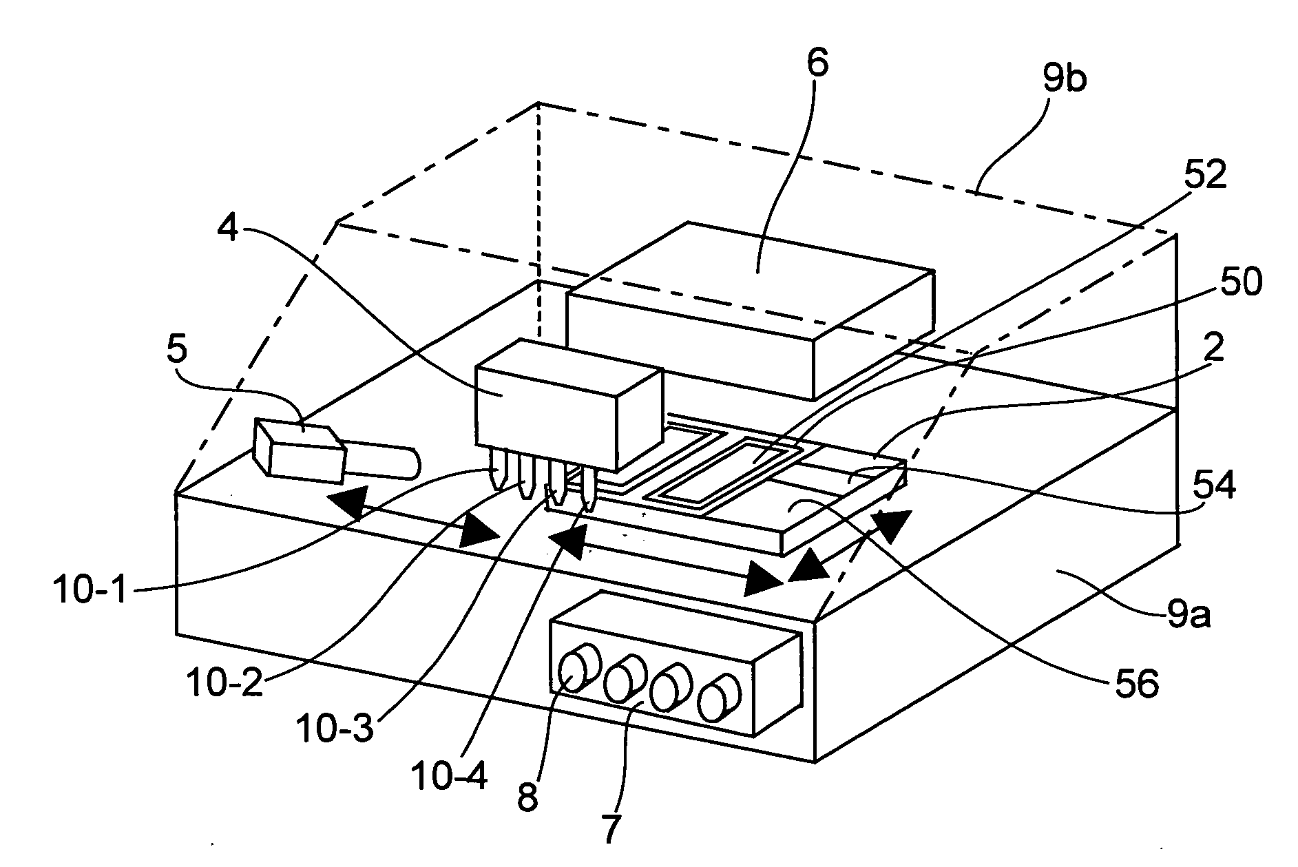
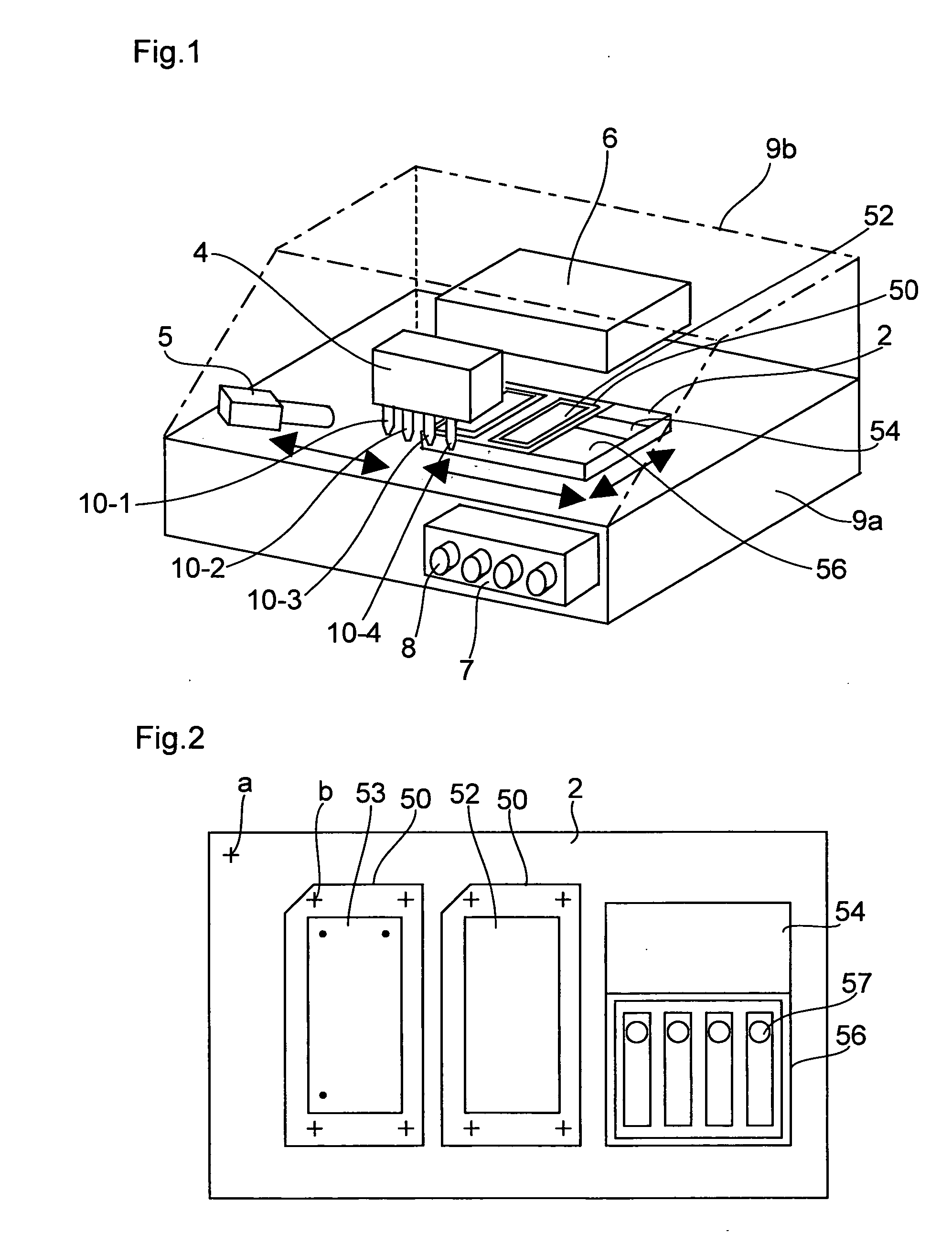
[0100]FIG. 1 schematically illustrates an embodiment of a liquid dispensing apparatus according to the present invention.

[0101] Reference numeral 4 denotes a print head which is a dispensing mechanism and includes four dispensing devices 10-1 to 10-4 arranged in a row and mounted thereto, each dispensing device including a piezo device for dispensing a reagent, etc. The dispensing devices 10-1 to 104 are in fixed positions. In order to control the amounts of liquid dispended from the dispensing devices 10-1 to 10-4, a pressure control section 7 for adjusting the pressure applied on the dispensing devices is mounted to the front surface of the apparatus main body, and four knobs 8 for adjusting the pressures within the dispensing devices 10-1 to 10-4 are arranged in correspondence with the respective dispensing devices 101 to 10-4.

[0102] A scanner 6, as an image capturing device, is placed for capturing images of a table and sample plates onto which liquid is to be dispensed. The s...


PUM

PropertyMeasurementUnit
angleaaaaaaaaaa
angleaaaaaaaaaa
shapeaaaaaaaaaa

Abstract

Methods and apparatuses for dispensing samples or reagents onto a target object are provided. A dispensing position designating section (62) designates the dispensing position on the target object (50), such as a membrane, based on an image of the target object (50) displayed on a monitoring section (60). A dispensing control section (64) positions the target object and the dispensing device relative to each other so that the designated dispensing position on the target object is placed beneath the dispensing device (10) and controls the dispensing operation of the dispensing device (10). A dispensing position information creating section (68) creates dispensing position information about the dispensing position on the target object (50) which is designated by the dispensing position designating section (62) and to which the dispensing operation has been performed and outputs it to the outside.

Description

BACKGROUND OF THE INVENTION [0001] 2. Field of the Invention [0002] The present invention relates to methods and apparatuses for dispensing samples or reagents in analysis apparatuses for use in the fields of chemistry, industry, clinical technology, and biotechnology. [0003] 2. Description of the Related Art [0004] Laser desorption / ionization mass spectrometry methods have been performed which apply laser light to samples placed on sample plates mounted in a mass spectrometry apparatus to ionize and analyze the samples. Some of the spectrometry methods employ matrix in creating samples on sample plates, while other spectrometry methods employ no matrix. [0005] The methods which combine such spectrometry methods employing matrix and a time of flight mass spectrometry apparatus are called MALDI-TOF (matrix-assisted laser desorption / ionization mass spectrometry-time of flight) mass spectrometry methods. In MALDI-TOFs, a test sample is dripped onto sample plates along with a matrix sol...

Claims


Application Information

Patent Timeline
Patent Type & Authority Applications(United States)
IPC IPC(8): B05C11/00C23C16/52G01N1/10G01N35/00B01L3/02G01N35/10
CPCB01L3/0268B01L3/0275B01L2200/143B01L2200/148B01L2300/0832B01L2400/0439G01N35/1011G01N35/1016G01N2035/1041
Inventor HANAFUSA, NOBUHIROSUGIYAMA, KIYOHIROFURUTA, MASARUYAMAGUCHI, RYOAKINAGA, NOBUYUKIMIYAMOTO, KEISUKEKONOSHITA, RYUH
Owner SHIMADZU CORP
Learn More