
Optical isolator

a technology of optical isolators and isolators, applied in non-linear optics, instruments, optics, etc., can solve the problems of difficult identification of optical signals, insufficient adaptability of conventional isolators to different requirements for different applications, and the isolator core complicates the assembly process of isolators, so as to simplify the assembling process of optical isolators and expand the application of optical isolators.

Inactive Publication Date: 2006-07-06
KAIWOOD TECH
View PDF4 Cites 2 Cited by
  • Summary
  • Abstract
  • Description
  • Claims
  • Application Information

AI Technical Summary

Benefits of technology

[0013] The present invention is aimed to provide an optical isolator, which dissolves the above-mentioned problems, simplifies the assembling process of optical isolators, and allows for arbitrary combination of an optical isolator with other optical component to thereby expanding the applications of the optical isolator.
[0016] The core device of optical isolator in accordance with the present invention comprises a polarizer and a polarization-rotating device. The polarizer is made of commonly used birefringent crystal, such as rutile, calcite, lithium niobate (LiNbO3), and yttrium vanadate (YVO4). The polarization-rotating device is made of commonly used magneto-optical crystal, such as paramagnetic glass and yttrium iron garnet (YIG). Also, the polarizer and the polarization-rotating device can be of any desired thickness, which allows the polarizer and the polarization-rotating device to be made with different characteristics of polarization and optical activity.
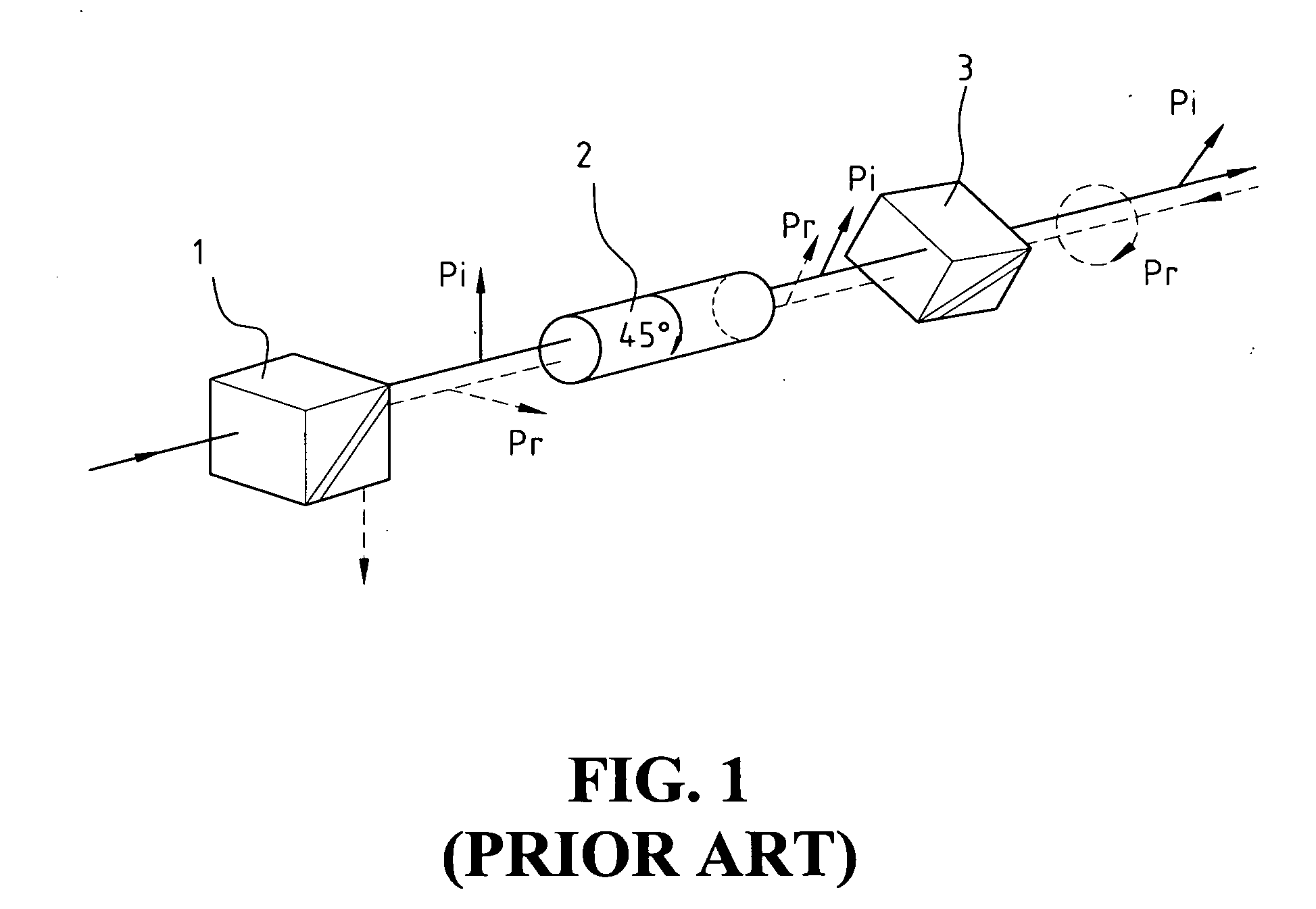
[0017] In practice, a number of the core devices in accordance with the present invention can be selectively jointed or combined with other optical devices, such as polarizers and polarization-rotating devices of different types, to form optical isolators of desired characteristics. The core device of the present invention is a modularized device, which allows the device to be calibrated for any desired angle and gives the device flexibility in different applications. In addition, the core device of the present invention has a simple structure, which simplifies the manufacturing process and reduces defect rate of product.

Problems solved by technology

This often results in chaos of identification of optical signals.
However, the increased number of components for the isolator core complicates the assembly process of isolator for increased workload for high precision calibration and alignment of the components is required.
This makes the conventional isolator not ready to satisfy different requirements for different applications.

Method used


Image

  • Optical isolator
  • Optical isolator
  • Optical isolator

Examples


Embodiment Construction

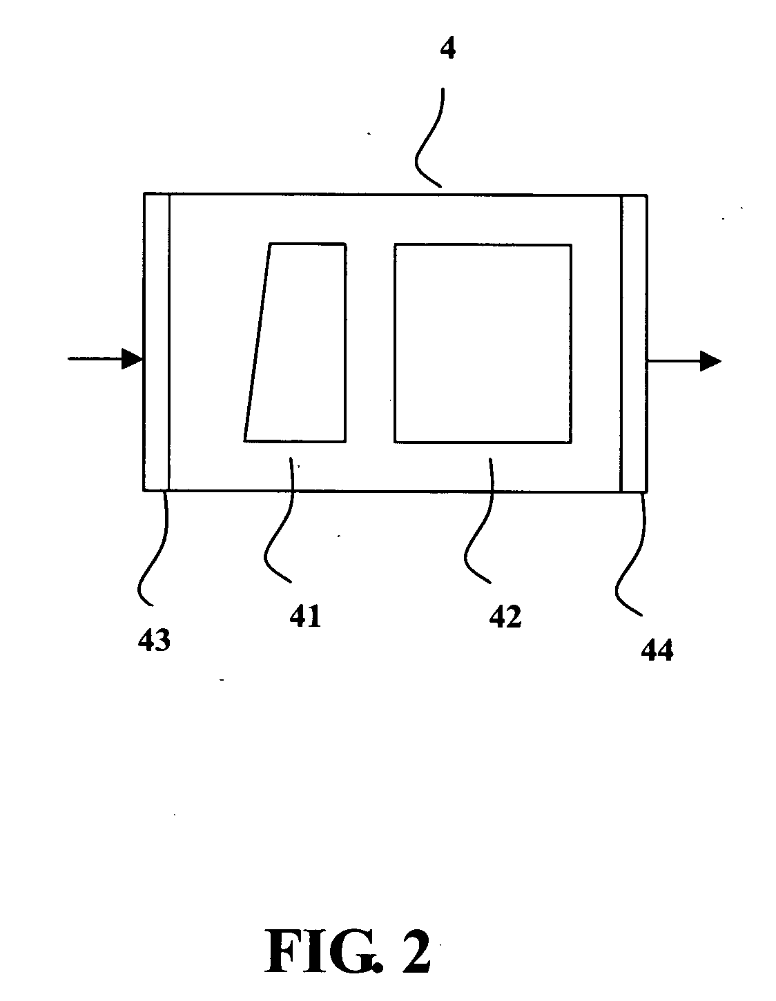
[0023] With reference to the drawings and in particular to FIG. 2, a core device constructed in accordance with the present invention, generally designated with reference numeral 4, comprises a polarizer 41 and a polarization-rotating device 42. In accordance with the present invention, the polarizer 41 and the polarization-rotating device 42 are integrated together as a modularized device. The core device 4 also comprises an optical input port 43 and an optical output port 44 at opposite ends of the device 4 and adjacent to the polarizer 41 and the polarization-rotating device 42, respectively.

[0024] It is noted that the arrows in FIG. 2, as well as other drawings attached herein, represent the traveling direction of light.

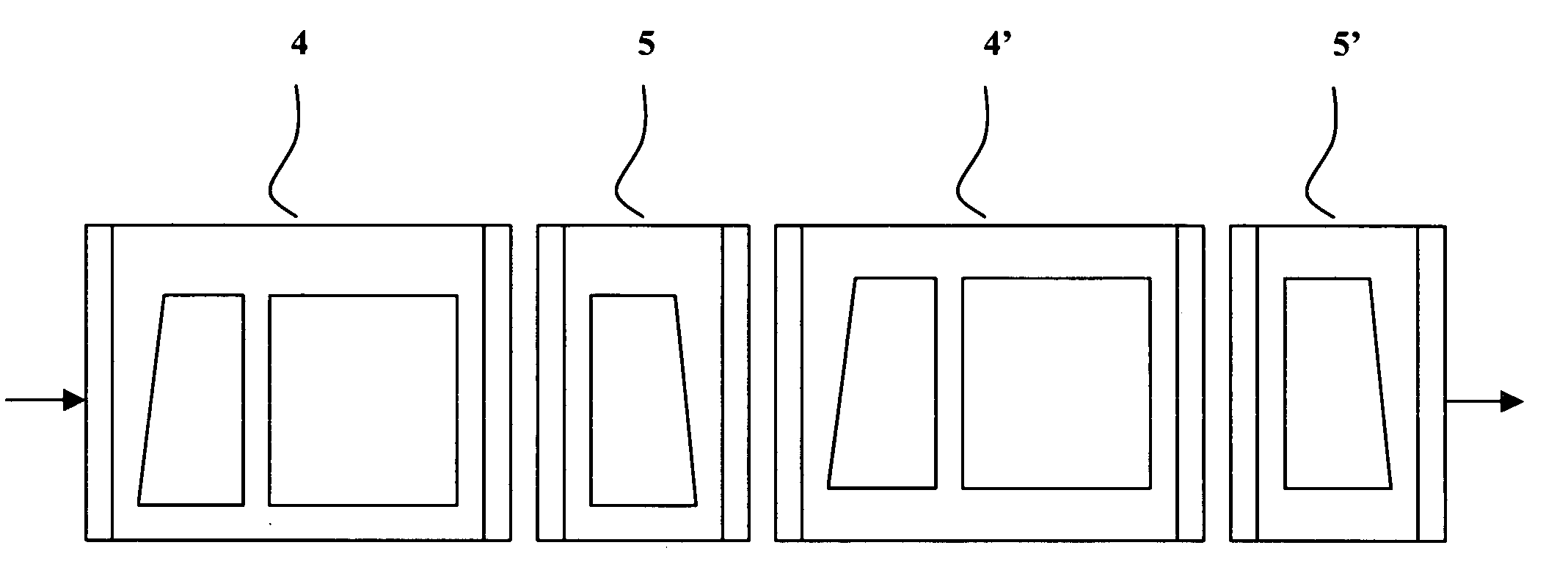
[0025] Also referring to FIG. 3, which shows an optical isolator incorporating the core device 4 of the present invention, the optical isolator comprises an optical component 5 jointed to the core device 4 to form a “fundamental” optical isolator. The optical c...


PUM

PropertyMeasurementUnit
lengthaaaaaaaaaa
lengthaaaaaaaaaa
angleaaaaaaaaaa

Abstract

A core device of optical isolator comprises a polarizer and a polarization-rotating device, which are integrated together as a modularized device. The modularized core device can be combined with other optical components to provide optical isolators of desired characteristics. With the modularized core device, the assembling of optical isolator is simplified and combination with other component is enhanced, thereby extending the applications of the core device.

Description

BACKGROUND OF THE INVENTION [0001] 1. Field of the Invention [0002] The present invention relates to an optical isolator, and in particular to a modularized core device of the optical isolator, featuring easy assembling and combination with other optical components to provide optical isolators satisfying different requirements. [0003] 2. The Prior Arts [0004] Because of advantages of small loss of signals, high capacity, high transmission speed, free from EMI, high security, little mass, and small volume, optical communication has been one of the most prosperous sectors of communication industry since 1970s. Thanks to the invention of optical fiber and the development of semiconductor laser, the optical communication gradually plays an important role in all fields of communication business, including long-distance sea cables, local area phone trunks, computer data networks, and optical fibers for CATV / coaxial cable hybridized wiring network. The application of the optical communicat...

Claims


Application Information

Patent Timeline
Patent Type & Authority Applications(United States)
IPC IPC(8): G02F1/09
CPCG02F1/093G02F2202/40G02F2203/07
Inventor CHUANG, TSUNG-KAICHOI, MEI-LENGWANG, JIANN-HUA
Owner KAIWOOD TECH
Learn More