Integration of an electrical diode within a fuel cell

a fuel cell and diode technology, applied in the field of fuel cells, can solve the problems of low-performing cells experiencing cell overload, and cell overload, and achieve the effect of not increasing the thickness of the overall stack

Inactive Publication Date: 2006-07-06
GM GLOBAL TECH OPERATIONS LLC
View PDF5 Cites 11 Cited by
  • Summary
  • Abstract
  • Description
  • Claims
  • Application Information

AI Technical Summary

Benefits of technology

[0015] In accordance with the teachings of the present invention, a fuel cell system is disclosed that employs a diode electrically coupled between bipolar plates in each fuel cell of a fuel cell stack to prevent the fuel cell between the plates from reversing its polarity. In one embodiment, the diode is a thin-sheet p-n diode including doped semiconductor layers that has a thickness relative to the thickness of the MEA in the fuel cell so that the overall stack thickness does not increase. The diode has a predetermined characteristic so that when the fuel cell is operating pr...

Problems solved by technology

MEAs are relatively expensive to manufacture and require certain conditions for effective operation.
Because the cells are electrically coupled in series, a low performing cell may experience cell overload if the normal operating cells are able to supply a high stack load.
Cell overload can occur if the anode side of the fuel cell is starved for hydrogen, i.e., the amount of hydrogen being provided to the cell is not enough to provide the desired power output.
This condition may be permanently detrimental to the performance of the overloaded cell, and in turn the entire stack.
The simultaneous presence of hydrogen and oxygen on the cathode side is undesirable and can ...

Method used


Image

  • Integration of an electrical diode within a fuel cell
  • Integration of an electrical diode within a fuel cell
  • Integration of an electrical diode within a fuel cell

Examples


Embodiment Construction

[0021] The following discussion of the embodiments of the invention directed to a fuel cell employing a diode for preventing fuel cell polarity reversal is merely exemplary in nature and is in no way intended to limit the invention or its applications or uses.

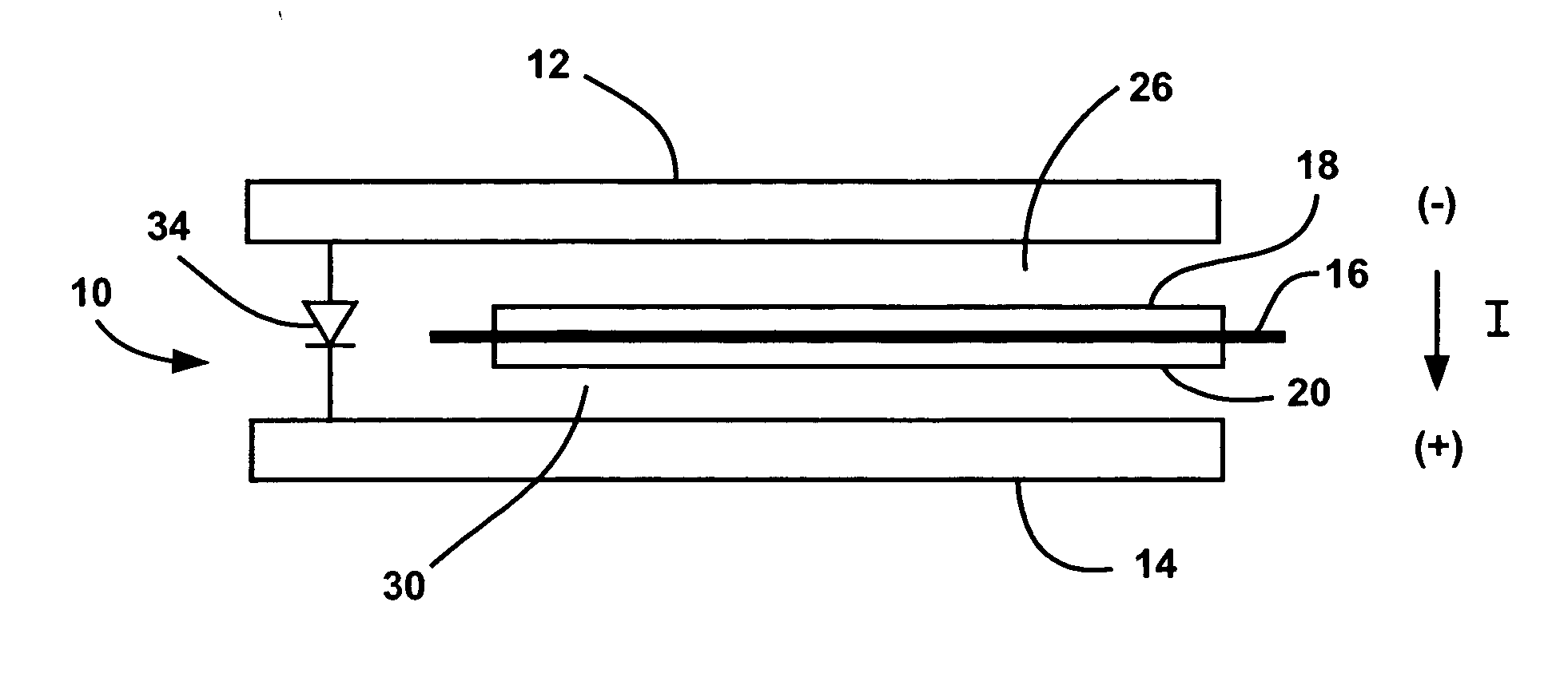
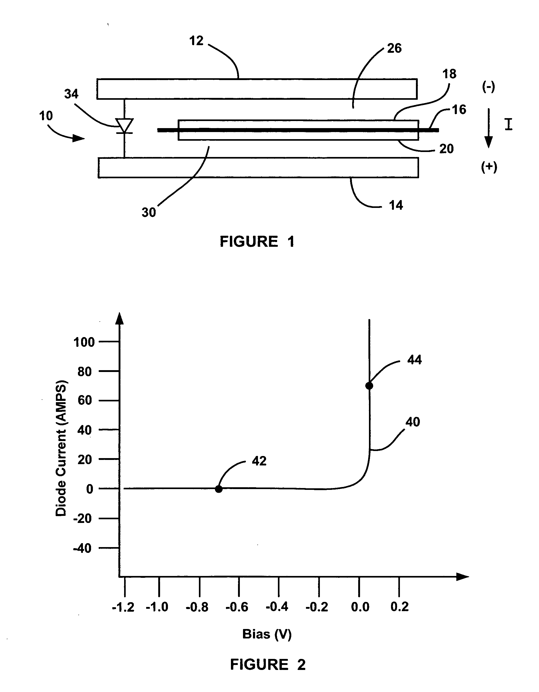
[0022]FIG. 1 is a cross-sectional view of a fuel cell 10 that would be one fuel cell of a fuel cell stack, for example, a fuel cell stack in a vehicle. The fuel cell 10 includes an anode-side bipolar plate 12 and a cathode-side bipolar plate 14 having an MEA 16 positioned therebetween. The MEA 16 includes a membrane on which a catalyst is deposited so that a catalyst layer of the MEA 16 faces both of the bipolar plates 12 and 14. In this example, an anode side of the bipolar plate 12 faces the MEA 16 and a cathode side of the bipolar plate 14 faces the MEA 16. The cathode side of the bipolar plate 12 would face the MEA of another fuel cell in the stack on one side of the fuel cell 10 and the anode side of the bipolar plate 14 ...


PUM


Abstract

A fuel cell system that employs a diode electrically coupled between bipolar plates in a fuel cell of a fuel cell stack for preventing the fuel cell between the plates from reversing its polarity. The diode is a thin-sheet p-n diode including doped semiconductor layers and has a thickness relative to the thickness of the MEA in the fuel cell so that the overall stack thickness does not increase. When the fuel cell is operating properly the diode does not conduct and all of the current through the fuel cell goes through the MEA. If the electric load on the stack increases to a level beyond the capability of the fuel cell, where the potential across the fuel cell goes significantly below zero, the diode will begin to conduct so that any current that cannot travel through the MEA with the cell voltage less than one negative forward diode voltage drop is able to go around the MEA through the diode.

Description

BACKGROUND OF THE INVENTION [0001] 1. Field of the Invention [0002] This invention relates generally to a fuel cell and, more particularly, to a fuel cell that includes a thin-sheet diode electrically coupled to bipolar plates in the cell for preventing a polarity reversal of the fuel cell. [0003] 2. Discussion of the Related Art [0004] Hydrogen is a very attractive fuel because it is clean and can be used to efficiently produce electricity in a fuel cell. The automotive industry expends significant resources in the development of hydrogen fuel cells as a source of power for vehicles. Such vehicles would be more efficient and generate fewer emissions than today's vehicles employing internal combustion engines. [0005] A hydrogen fuel cell is an electrochemical device that includes an anode and a cathode with an electrolyte therebetween. The anode receives hydrogen gas and the cathode receives oxygen or air. The hydrogen gas is dissociated in the anode to generate free protons and ele...

Claims


Application Information

Patent Timeline
IPC IPC(8): H01M8/04H01M8/10H01M8/24
CPCH01M8/0202H01M8/04552H01M8/04753H01M8/0494H01M8/1002H01M8/241Y02E60/50H01M8/1007H01M8/2457
Inventor MURPHY, MICHAEL W.MATHIAS, MARKCHOW, DAVID
Owner GM GLOBAL TECH OPERATIONS LLC
Why Eureka
Try Eureka