
A method for autonomic control of a manufacturing system

a manufacturing system and autonomic control technology, applied in the field of autonomic control of a manufacturing system, can solve problems such as poor or infeasible choi

Inactive Publication Date: 2006-07-06
IBM CORP
View PDF15 Cites 18 Cited by
  • Summary
  • Abstract
  • Description
  • Claims
  • Application Information

AI Technical Summary

Benefits of technology

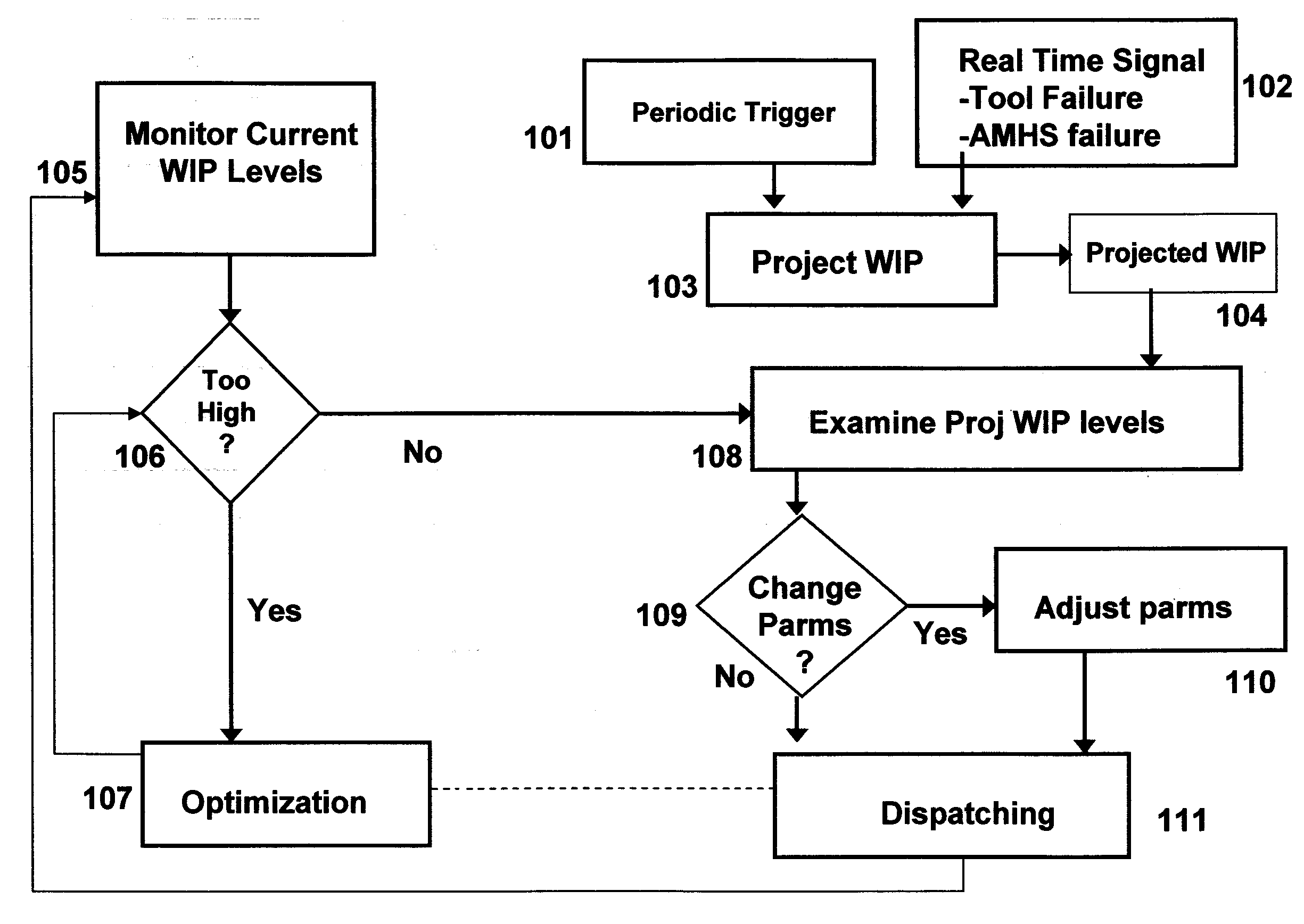
[0009] The process of projecting the future levels of partially completed products that will be available for dispatch to the tool is based on measurements of tool usage in the manufacturing system, product routing information, partially completed products availability, processing cycle time information, operational failures in the manufacturing system and optionally an Automated Materials Handling System (AMHS) that will effect the partially completed products before the partially completed products are sche

Problems solved by technology

However, in semiconductor manufacturing, there are various tool-specific and lot specific scheduling attributes which make this a poor or infeasible choice.

Method used


Image

  • A method for autonomic control of a manufacturing system
  • A method for autonomic control of a manufacturing system
  • A method for autonomic control of a manufacturing system

Examples


Embodiment Construction

[0015] The present invention and the various features and advantageous details thereof are explained more fully with reference to the nonlimiting embodiments that are illustrated in the accompanying drawings and detailed in the following description. It should be noted that the features illustrated in the drawings are not necessarily drawn to scale. Descriptions of well-known components and processing techniques are omitted so as to not unnecessarily obscure the present invention. The examples used herein are intended merely to facilitate an understanding of ways in which the invention may be practiced, and to further enable those of skill in the art to practice the invention. Accordingly, the examples should not be construed as limiting the scope of the invention.

[0016] All manufacturing lines have instances of unbalance in which work in process inventory (WIP) is not uniformly distributed across the system, but rather is accumulated in front of one or more particular manufacturin...


PUM


Abstract

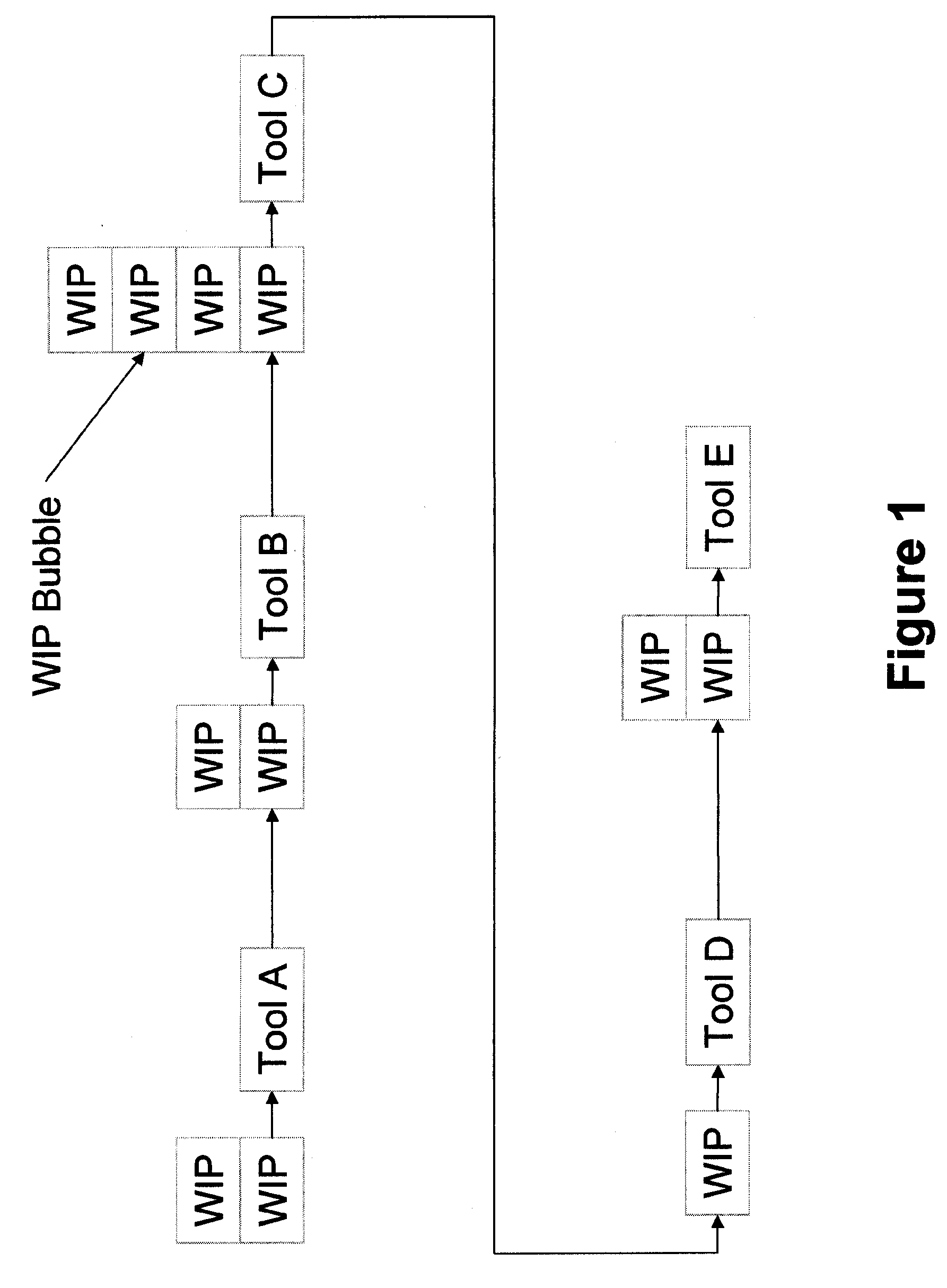
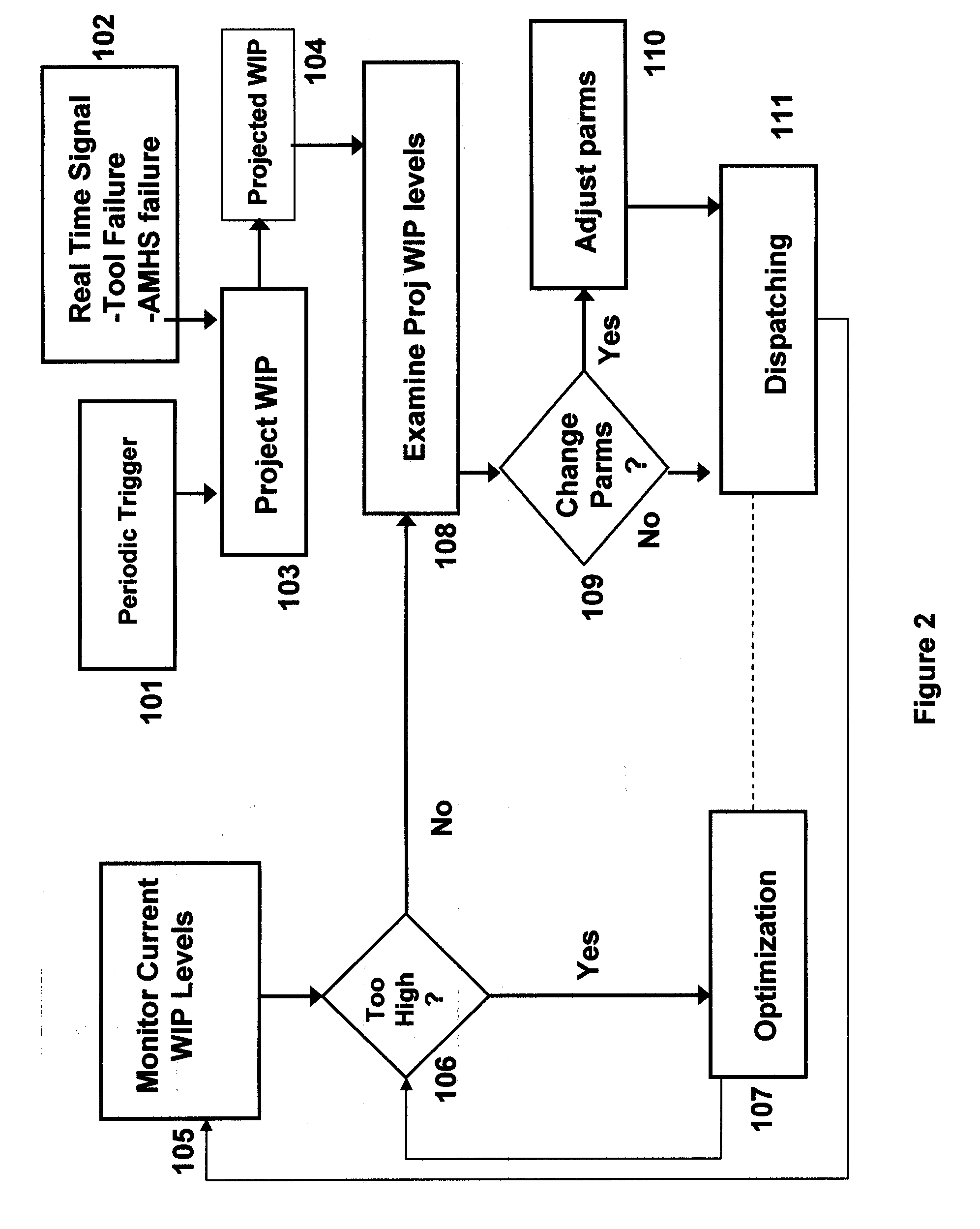
Disclosed is a method of controlling a manufacturing system. The invention automatically monitors current levels of partially completed products waiting to be processed by a tool (or group of tools) and determines whether the current levels exceed a predetermined limit. If the current levels do exceed the predetermined limit, the invention performs an optimization process. However, if the current levels do not exceed the predetermined limit, the invention performs a dispatching process. In this dispatching process, the invention automatically projects future levels of partially completed products that will be supplied to the tool to identify a future work-in-process (WIP) bubble. The WIP bubble occurs when larger than normal amounts of partially completed products are supplied to the tool. The invention automatically adjusts the operating parameters of the tool based upon both the current levels and the future levels.

Description

BACKGROUND OF THE INVENTION [0001] 1. Field of the Invention [0002] The present invention relates to computer implementable decision support systems for determining factory schedules and dispatching systems for determining job priorities. General methodologies within this field of study include advanced planning systems, optimization and heuristic based algorithms, constraint based programming, simulation, and autonomic control. [0003] 2. Description of the Related Art [0004] The dispatching of production lots is a critical activity for smooth and reliable operation of a manufacturing system. Shop floor software scheduling systems are used to decide the sequence of a set of queued lots to dispatch to a given tool in the manufacturing line. For simple manufacturing systems, a first-in-first-out (FIFO) rule is often a reasonable choice. However, in semiconductor manufacturing, there are various tool-specific and lot specific scheduling attributes which make this a poor or infeasible c...

Claims


Application Information

Patent Timeline
IPC IPC(8): G06F19/00
CPCG05B19/41865G05B2219/31411G05B2219/32247G05B2219/32267G05B2219/32271G05B2219/32293G05B2219/45028Y02P90/02
Inventor DENTON, BRIAN T.FORDYCE, KENNETH J.MILNE, ROBERT J.
Owner IBM CORP
Learn More