AI technical title is built by Patsnap AI team. It summarizes the technical point description of the patent document.
a scanning probe and microscopy technology, applied in the field of microelectromechanical systems, can solve the problems of inability to provide more effective gas and vacuum delivery techniques, and achieve the effect of enhancing nanomachining operations and enhancing measuring functions
Inactive Publication Date: 2006-07-13
TERRASPAN
View PDF4 Cites 4 Cited by
Summary
Abstract
Description
Claims
Application Information
AI Technical Summary
This helps you quickly interpret patents by identifying the three key elements:
Problems solved by technology
Method used
Benefits of technology
Benefits of technology
"The patent describes a device that uses fluidic channels to perform various tasks, such as measuring and nanomachining. The device has one or more isotopic regions that provide power to the workpiece, which enhances the measuring function and nanomachining operations. The technical effect of this invention is improved accuracy and efficiency in measuring and nanomachining processes."
Problems solved by technology
To date, no suitable techniques exist to provide for more effective gas and vacuum delivery in the proximity of a site being worked by a nanomachining process.
Method used
Image
Click on the blue label to locate the original text in one second.
Reading with bidirectional positioning of images and text.
Examples
Embodiment Construction
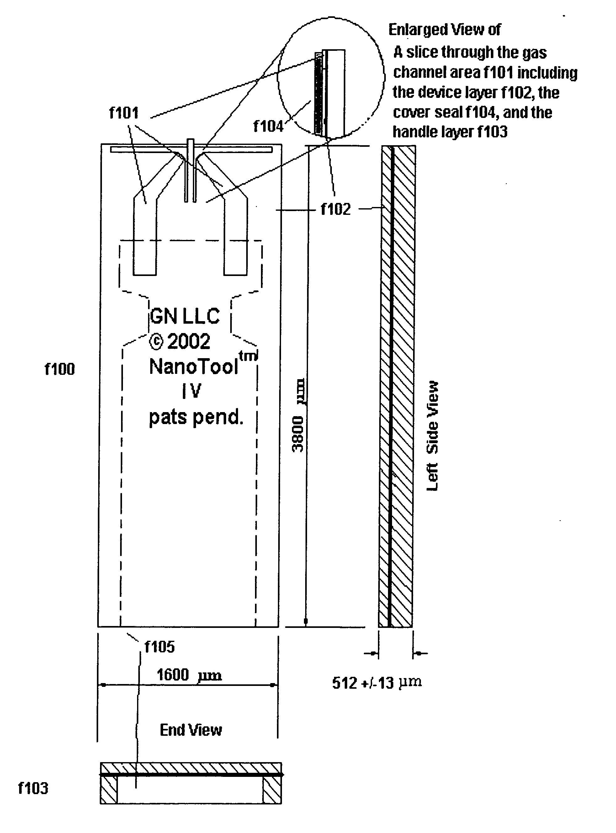
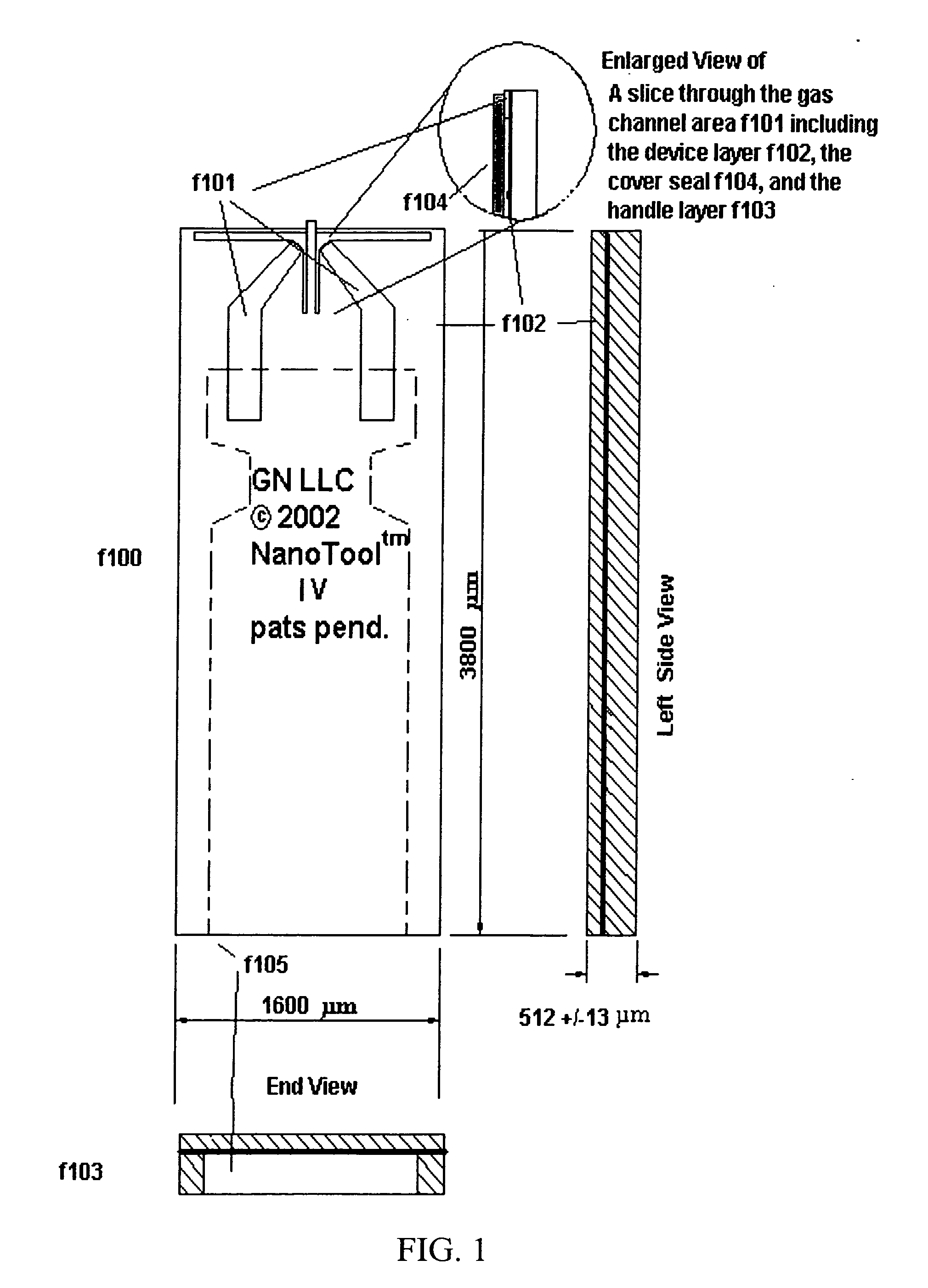
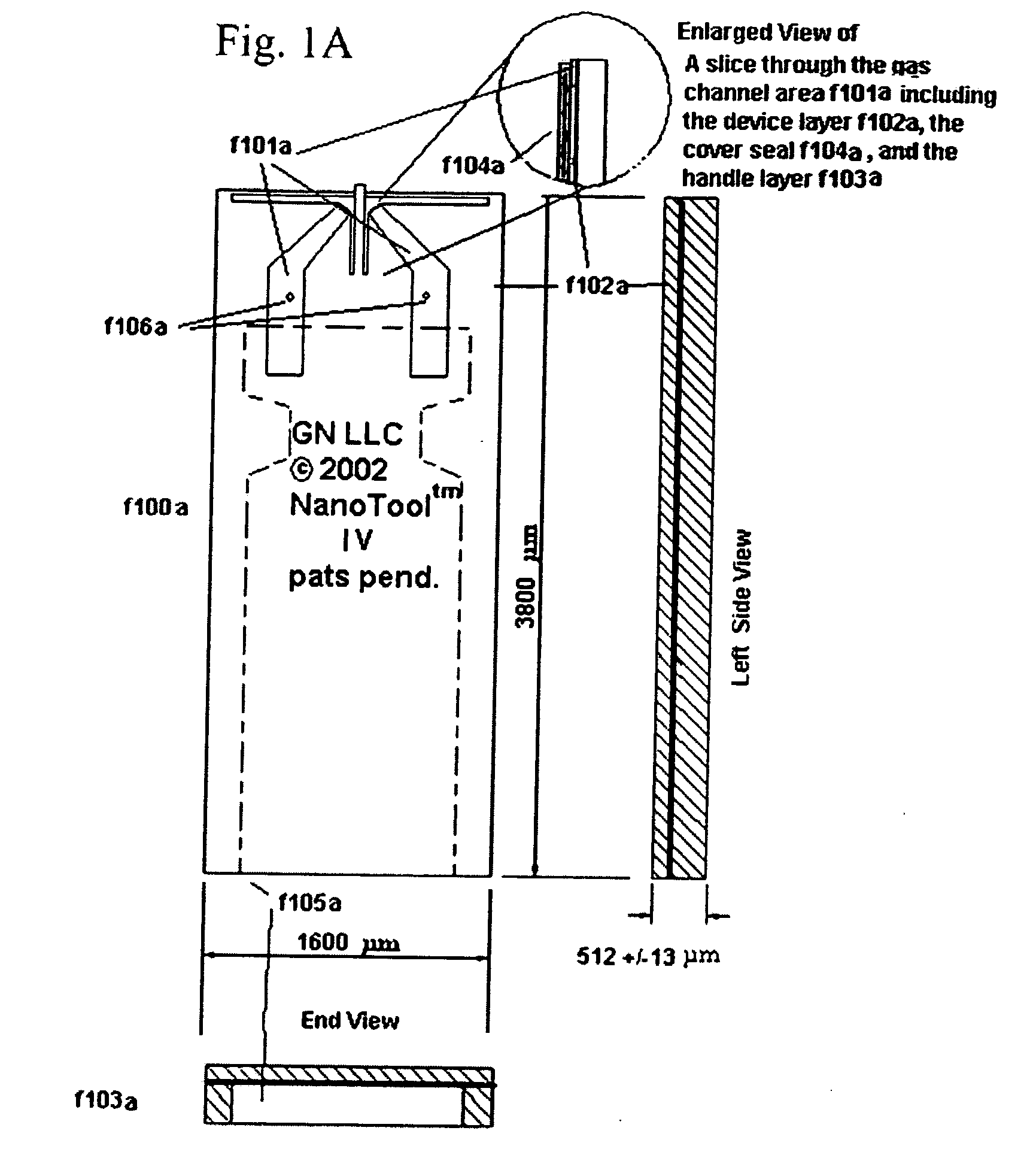
[0025]FIG. 1 shows an SOI (silicon on insulator) MEMS cantilever f100 having gas channels f101 formed in the device layer. Each channel is fed via a recess f105 (shown in phantom) formed in the body of in the handle layer f103 of the cantilever f100. The recess is therefor in fluid communication with the channels f101. Gas introduced through the floor plate or gas feed tube (not shown) from a gas source (not shown) is thereby delivered via the recess f105 to the channels f101 and finally to a region of the tip at the end of the cantilever f100.
[0026] As can be seen in the enlarged view, a cover seal (or cover layer) f104 can be provided to contain the gas pressure that can be developed at the tip. In one embodiment, the cover seal can be any suitably patterned thin material including adhesive plastic films, silicon cover structure, or diamond film cover structure. These latter materials may be bonded by coating with Titanium, Nickel and Copperlayers to make a Coppervacuum furnace...
PUM
Property
Measurement
Unit
radioactivity
aaaaa
aaaaa
current
aaaaa
aaaaa
electrical power
aaaaa
aaaaa
Abstract
The following invention pertains to the introduction of a gas (or fluid) around a SPM probe or nanotool™ to control chemical activity e.g. oxygen to promote oxidation, argon to inhibit oxidation or clean dry air (CDA) to inhibit moisture to control static charging due to the action of the probe or nanotools and to provide vacuum at and around the tip and substrate area. The invention can also produce electrical current for use with active electronic devices on, in or near the body of the device. In addition by use of a fluid like water, certain oils, and other liquids in conjunction with specific tip structure either electric dischargemachining can be used at the tip area on the tip itself (in conjunction with a form structure on the work piece) or on a work piece beneath the tip to shape, polish and remove material at very small scales (10 microns to 1 nm or less).
Description
CROSS-REFERENCES TO RELATED APPLICATIONS [0001] This application is a Divisional Application of U.S. application Ser. No. 10 / 659,737, filed Sep. 9, 2003, which claims priority from U.S. Provisional Application No. 60 / 409,403, filed Sep. 9, 2002 and from U.S. Provision Application No. 60 / 433,242, filed Dec. 12, 2002, all the disclosures of which are hereby incorporated by reference in their entirety for all purposes. [0002] This application is related to U.S. Application Nos.: [0003] Ser. No. 10 / 094,149, filed Mar. 7, 2002, now U.S. Pat. No. 6,802,646; [0004] Ser. No. 10 / 094,411, filed Mar. 7, 2002, abandoned; [0005] Ser. No. 10 / 094,408, filed Mar. 7, 2002, now U.S. Pat. No. 6,923,044; [0006] Ser. No. 10 / 093,842, filed Mar. 7, 2002; [0007] Ser. No. 10 / 094,148, filed Mar. 7, 2002, now U.S. Pat. No. 6,752,008; and [0008] Ser. No. 10 / 228,681, filed Aug. 26, 2002, now U.S. Pat. No. 6,880,388 the disclosures of which are hereby incorporated by reference for all purposes.BACKGROUND OF THE...
Claims
Application Information
Patent Timeline
Application Date:The date an application was filed.
Publication Date:The date a patent or application was officially published.
First Publication Date:The earliest publication date of a patent with the same application number.
Issue Date:Publication date of the patent grant document.
PCT Entry Date:The Entry date of PCT National Phase.
Estimated Expiry Date:The statutory expiry date of a patent right according to the Patent Law, and it is the longest term of protection that the patent right can achieve without the termination of the patent right due to other reasons(Term extension factor has been taken into account ).
Invalid Date:Actual expiry date is based on effective date or publication date of legal transaction data of invalid patent.
Patent Type & AuthorityApplications(United States)

