[0008] Proceeding from aforementioned, the present invention is based on the object of improving the rotary
internal combustion engine by way of providing rotational couplings between each of
satellite gears and the flywheel and the bearing member, with inclusion of axial bearings for
satellite gears in the transmission gear, thereby allowing to eliminate
impact loads on the components of said transmission gear, to reduce loads on said components and
power consumption required for overcoming friction in said components, and to provide more flexible couplings therebetween, and hence to increase the
performance index of the engine, reliability and interrepair time thereof, while reducing dimensions and
mass of the components of the transmission gear, and to extend the capabilities of setting the mode of variation of the speed of relative travel of the bearing members.
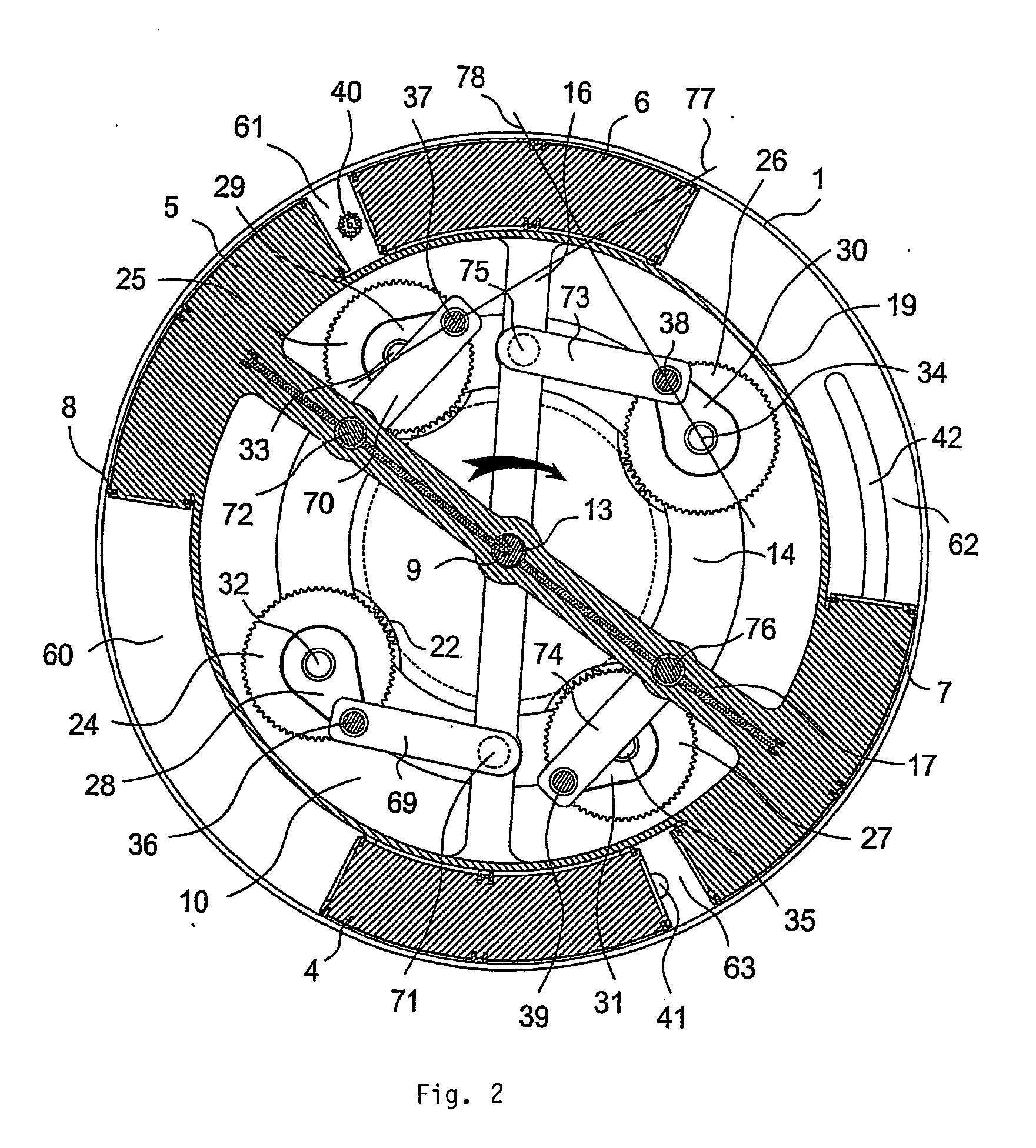
[0010] Provision of the transmission gear with four instead of two eccentric members mounted with main journals thereof within four openings provided in the flywheel and having no rigid
coupling therebetween, and availability of couplings between the crankpins and the bearing members via the coupler links result in
elimination of the
crankpin—radial slot pairs that operate under conditions of
kinetic friction and great contact loads, thereby imparting all the couplings between the bearing members and the flywheel rotational nature and making them more loose, which results in a decrease in consumption of energy required to overcome the friction between the components of the transmission gear, and expands the possibilities of setting a mode of variation of the speed of relative travel of the bearing members provided with the pistons. At the same time, the above rotational couplings eliminate abrasion of interacting surfaces and resulting emergence of
impact loads within the transmission gear. Fastening of the main journals within the
satellite gears along axes of rotation thereof results in the reduction of loads, and hence of the friction in toothed meshes, and eliminates any substantial alternate stresses in the transmission gear components. All this permits to reduce costs required to overcome the friction between the transmission gear components, to reduce the loads exerted thereon, and hence to increase the
performance index of the engine, reliability and interrepair life thereof, while decreasing dimensions and
mass of the transmission gear components.
[0011] In so doing, the bearing members of the inventive
rotary engine may be disposed on both sides of the
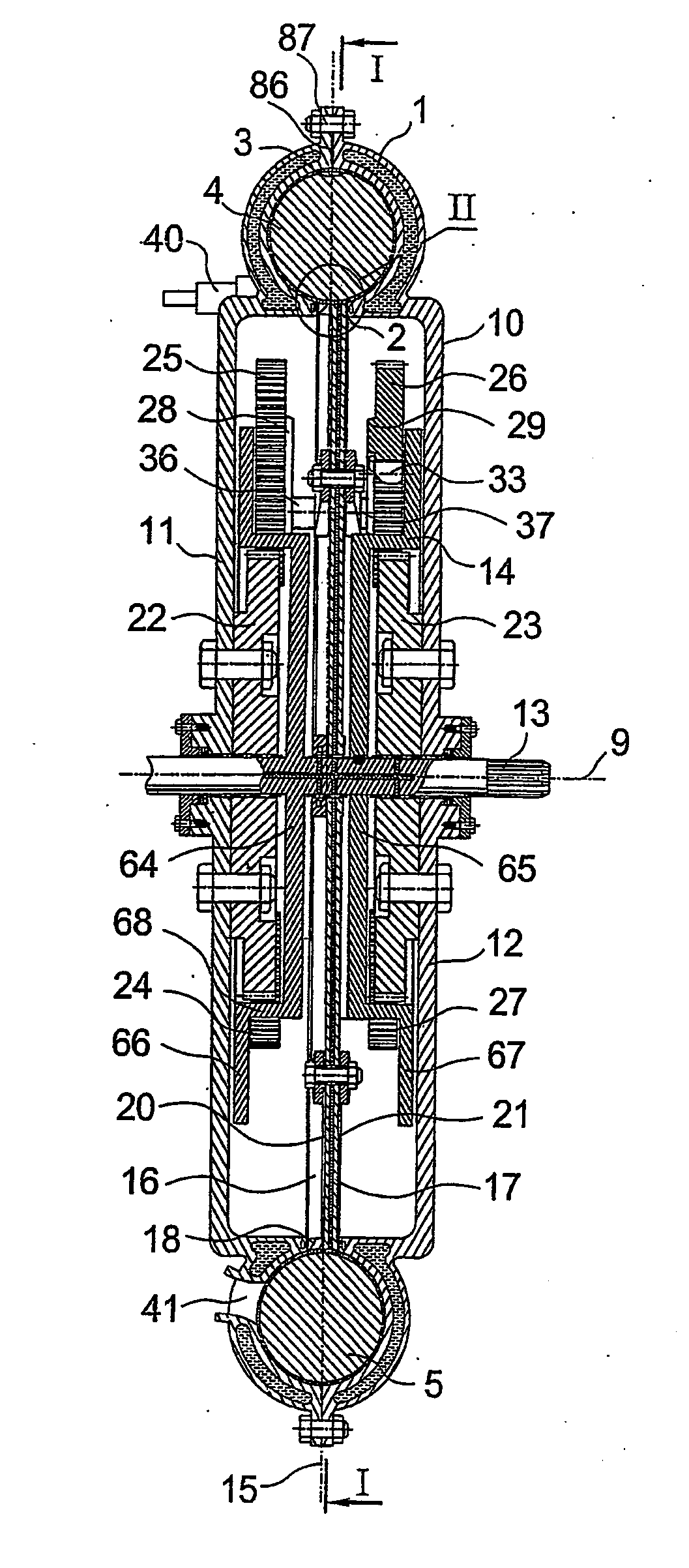
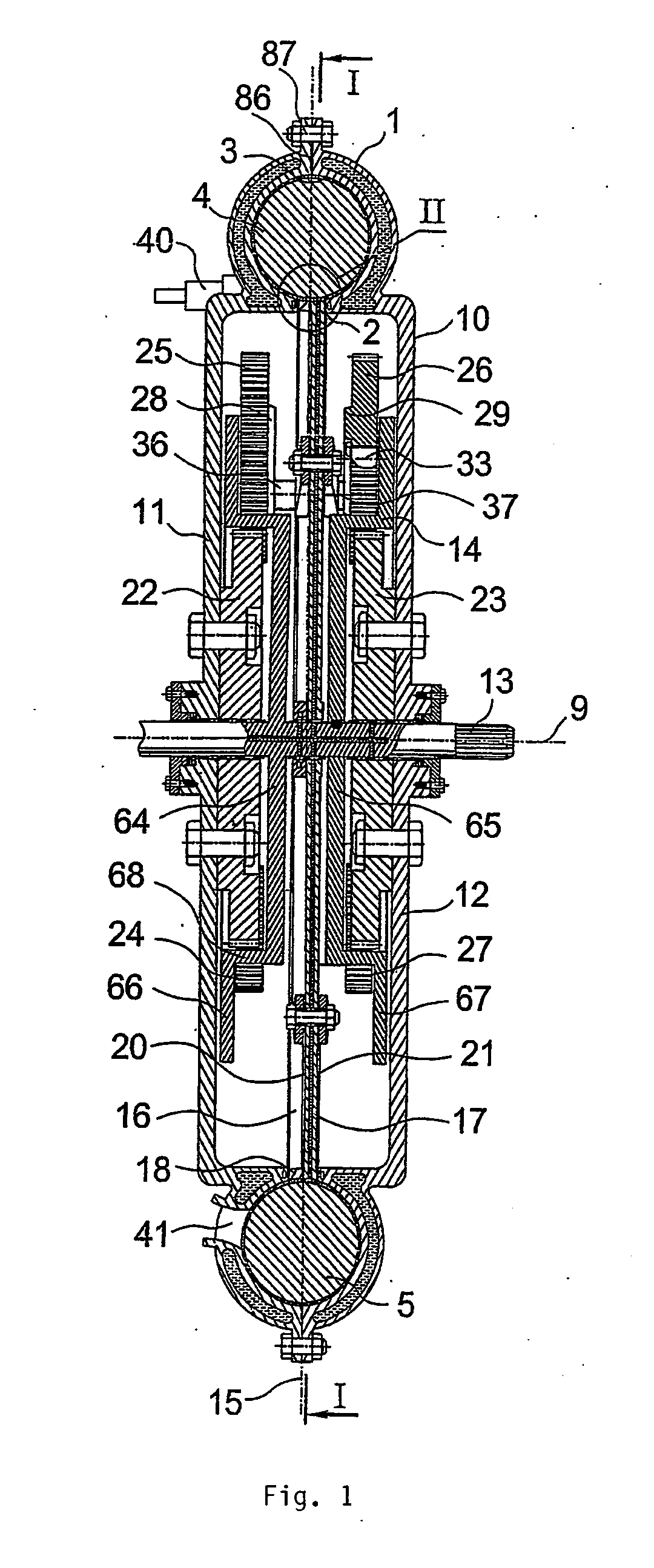
central plane of the cylinder, with a gap provided between the walls of said bearing members; the flywheel is composed of two radially arranged discs, each of them being disposed between one of the toothed gearwheels and one of the bearing members, and two radially arranged rings, each of them being disposed between one of the housing side walls and one pair of the satellite gears, and coupled with one of the discs by means of two arc-shaped plates passed between the points of engagement of toothed gearwheels with satellite gears, the main journals of the satellite gears meshed with one toothed gearwheel being mounted within the openings of one ring, and the main journals of the satellite gears meshed with the other toothed gearwheel, within the openings of the other wheel. Such arrangement results in a small
axial length of the bearing members since their walls are disposed at an insignificant distance from one another in the axial direction; this however also somewhat complicates the flywheel design, increases the number of parts, and complicates the technology of assembling such engine.
[0013] The
advantage of such embodiment of the engine consists in that the load on the teeth of satellite gears and toothed gearwheels, exerted by the bearing members, is evenly distributed between the twin gearwheels, thereby halving the load in the meshes between the satellite gears and the toothed gearwheels, and hence permitting to substantially reduce the sizes of the satellite gears and the toothed gearwheels, thereby decreasing radial dimensions of the transmission gear. In addition, making satellite gears in the twin form, their gearwheels being symmetrically arranged relative to the
central plane of the cylinder, ensures symmetrical arrangement of masses of the transmission gear components on both sides of this plane along axial and radial coordinates, and hence substantially simplifies static and dynamic balancing of the engine, and reduces the timetable and costs required for such balancing. This however somewhat complicates the design of the transmission gear and assembling of the engine.
[0014] As an alternative, the flywheel may be disposed in the
central plane of the cylinder, each toothed gearwheel being provided with a
bushing fastened on the side wall of the housing, and the bearing members are mounted for rotation on the bushings of the toothed gearwheels between these gearwheels and housing side walls. Such arrangement results in a substantial
axial length of the bearing members and their mounting on the bushings of the toothed gearwheels rather than on the output shaft, at the same time however simplifying the flywheel design and couplings thereof with satellite gears, and hence simplifies the technology of assembling such engine.
[0015] To ensure unhindered travel of the pistons within the cylinder and tightness of the inter-
piston chambers from the side of end faces of the pistons, external surfaces of the rings of the bearing members may be made along the moving line in the shape of a circular arc having a
diameter equal to the
diameter of the internal surface of the working cylinder, and the rings are mounted within the circular slot, external surfaces thereof forming an extension of the internal surface of the cylinder. Such arrangement results in a complicated shape of external surfaces of the rings, thereby requiring a high working accuracy and precise fitting of these surfaces to the internal surface of the cylinder in the process of mounting the rings inside the circular slot.

