Molding of slurry-form semi-solidified metal

a technology of semi-solid metal and die casting molding, which is applied in the direction of moulding machines, manufacturing tools,foundry moulding apparatus, etc., can solve the problems of difficult solidification and blowing off, high frequency of adhered metal remaining in the vessel, and nesting, so as to prevent a fall in runability, reduce the occurrence of nesting, and increase the yield of die casting

Active Publication Date: 2006-07-13
HONDA MOTOR CO LTD
View PDF2 Cites 15 Cited by
  • Summary
  • Abstract
  • Description
  • Claims
  • Application Information

AI Technical Summary

Benefits of technology

[0053] In the process of cooling the semi-solid metal, its viscosity is detected, and the solid phase percentage of the semi-solid metal is managed on the basis of this viscosity. Because the viscosity is detected, the influences of cooling rate changes and time can be eliminated, and the semi-solid metal solid phase percentage management accuracy can be raised much further than with related art management based on time.
[0080] With this die casting method, it is possible to suppress the occurrence of nesting by using a semi-solid metal as the casting material, and to achieve increases in cast molding yield because there is no breaking of sand cores. And, because in the gate and runner parts the semi-solid metal moves at a high speed for a short time, it is possible to prevent a fall in runability caused by hardening or the temperature falling.

Problems solved by technology

However, generally the properties of a metal change around its transition point, and inevitably a difference arises between the cooling rate before the transition point and the cooling rate after the transition point.
The air blowing means of these vessel restoring apparatuses of related art act so as to solidify semi-solid metal remaining adhered to the inner face of the vessel into a granular form and blow it off, but when semi-solid metal remains in relatively large lumps, it is difficult to solidify and blow these off.
When semi-solid metal has remained and solidified in large lumps, it is not possible to remove these by brushing means either, and the frequency of adhered metal remaining in the vessel becomes high.
As a result, it becomes necessary to anticipate restoring work outside the line and prepare a larger number of vessels, and this leads to an increase in initial cost.
However, when semi-solid metal remains inside the vessel in relatively large lumps, the vessel does not readily cool, the cooling of the vessel takes time, and this constitutes a problem in achieving productivity increases.
Here, when semi-solid metal adheres to a cooling metal of the stirring head and the next production of semi-solid metal is carried out with it still left there, solid matter having adhered to the cooling metal and solidified detaches in the vessel and quality deterioration of the semi-solid metal occurs, and plant trouble of solidified matter interfering with the vessel and so on arises.
When the cooling metal is dipped in water by the cooling means, the water flash-boils, and the energy of the flash-boiling causes adhered metal to detach and fall from the cooling metal.
It was thought that when the probe was dipped in water together with the cooling metal by the cooling means of the stirring head restoring apparatus described above, adhered metal would detach and fall from the probe under the energy of flash-boiling of the water; however, in practice, because compared to a cooling metal the heat capacity of a probe is extremely small, the energy of the flash-boiling around the probe is not strong enough for the adhered metal to detach and fall, and the adhered metal tended to remain on the probe.
And, the probe remains immersed in the water until the cooling metal has been cooled to the optimal temperature, and with this the problem also arises that the temperature of the probe, which has a small heat capacity, falls too far, and it is difficult for the releasing agent applied to dry in the subsequent coating step.
When the stirring time is extremely long, because the time for which the injection-molding machine is kept waiting becomes too long, productivity falls.
When the stirring time is extremely short, because the injection-molding machine becomes unable to keep up, it is necessary to limit the number of vessels circulated, and productivity falls.
Because in these closed deck type and semi-closed deck type cylinder blocks the water jacket is of a closed shape, at the time of casting it is not possible to use a durable trimming die for the water jacket, and a breakable core that can be crumbled and removed after casting, for example a sand core, is used.
Consequently, if a semi-solid metal is made to impact a sand core at a high speed, there is a risk of the sand core breaking.
In particular, a thin sand core for forming something like a water jacket will readily break when hit by a highly viscous semi-solid metal and yield of the product will fall.
To prevent breakage of a sand core during casting it is conceivable to lower the speed at which the semi-solid metal is poured, but when pouring takes a long time the semi-solid metal hardens, or as a result of its temperature falling its solid phase percentage changes, and there is a risk of the required run ability not being obtained.
As a result of the temperature falling the viscosity of the semi-solid metal becomes still higher, and again there is a risk of breaking the sand core.
If it were an ordinary melt, even when impacted at a high speed the sand core would not break; but when a semi-solid metal hits it at high speed there is a risk of it breaking, as mentioned above.
And when as in JP-A-9-57415 the pouring speed is made extremely low, the pouring time becomes long, and although with an ordinary melt there is no problem, with a semi-solid metal there is the concern that it will harden or its run ability will fall.

Method used


Image

  • Molding of slurry-form semi-solidified metal
  • Molding of slurry-form semi-solidified metal
  • Molding of slurry-form semi-solidified metal

Examples


Embodiment Construction

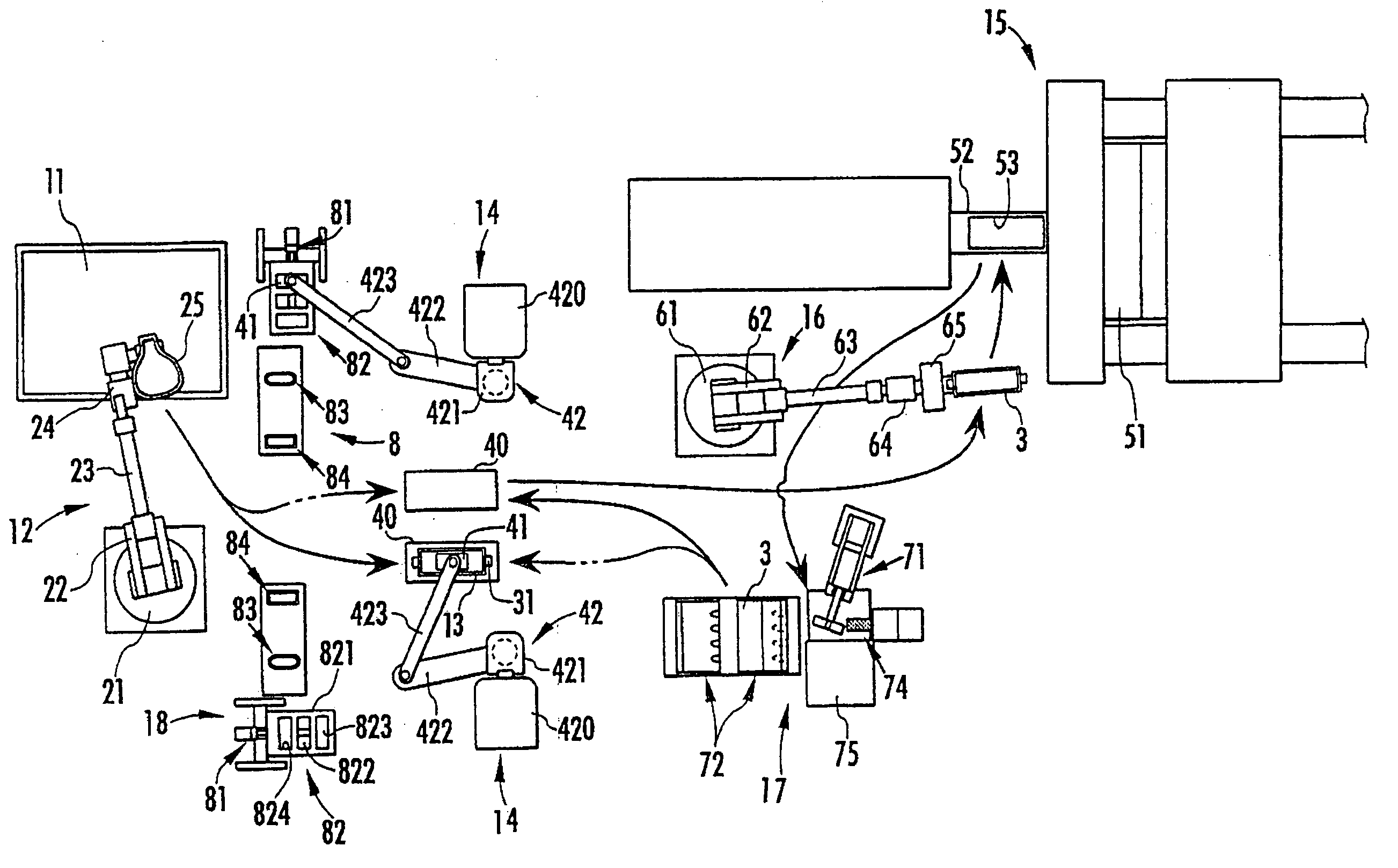
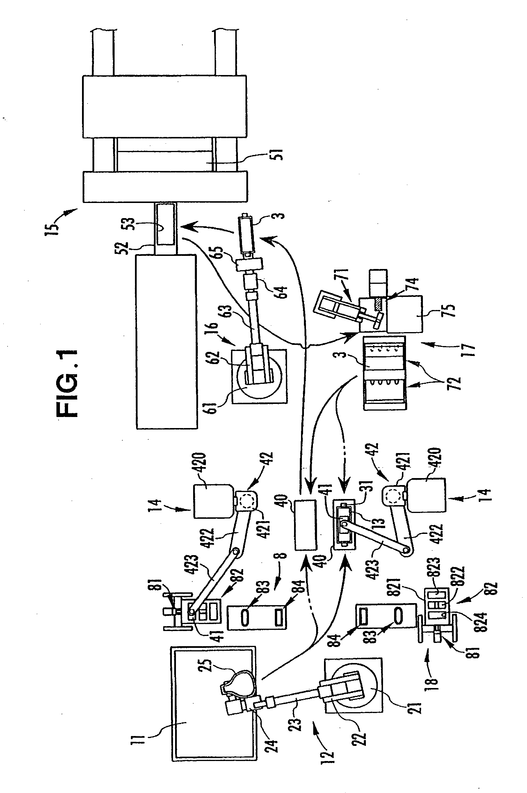
[0118]FIG. 1 shows a production line 10 of a molded metal product. This production line 10 has a melt holding furnace 11 for holding a melt consisting of a molten metal such as aluminum alloy; a melt scooping robot 12 for scooping out a predetermined amount of melt from inside the melt holding furnace 11; a vessel 13, rectangular in plan view, for pouring melt scooped out by the melt scooping robot 12; a semi-solid metal producing apparatus 14 for producing semi-solid metal by stirring and cooling the melt in the vessel 13; a molding machine 15 for molding a metal molded product with the semi-solid metal as a starting material; and a carrying robot 16 serving as a carrying apparatus for carrying the vessel 13 from the semi-solid metal producing apparatus 14 to the molding machine 15 and feeding the semi-solid metal in the vessel 13 into the molding machine 15. Also, the production line 10 is provided with a vessel restoring apparatus 17 for carrying out a restoration treatment on th...


PUM

PropertyMeasurementUnit
temperatureaaaaaaaaaa
immersion timeaaaaaaaaaa

Abstract

Made up of a step of preparing a map expressing a correlation between solid phase percentage and viscosity of a slurry-form semi-solid metal (27) for a given metal composition; a step of setting a target viscosity corresponding to a target solid phase percentage using this map; a viscosity measuring step of measuring the viscosity of a semi-solid metal in a vessel (13) while cooling it; and a step of carrying out cooling until this viscosity reaches the target viscosity, by these steps being carried out in from the preparation of the map expressing the correlation between solid phase percentage and viscosity of the semi-solid metal to the end of cooling of the semi-solid metal the solid phase percentage of the semi-solid metal is made to match the target solid phase percentage. Because the viscosity is detected, the affects of cooling rate changes and time can be eliminated, and it is possible to raise management accuracy of the solid phase percentage of the semi-solid metal much further than with related art management based on time.

Description

TECHNICAL FIELD [0001] This invention relates to the manufacture of a die cast molding using a slurry-form semi-solid metal such as an aluminum alloy. BACKGROUND ART [0002] Technology for die cast molding a metal melt such as an aluminum alloy is currently widely used, and recently, die casting methods using slurry-form semi-solid metal in which solid and liquid are both present together, regarded as suited to increasing mold life and increasing the dimensional accuracy of die cast moldings, have been receiving attention. [0003] In a die casting method using a semi-solid metal, management of solid phase percentage, which expresses the ratio of solid to liquid in the molten alloy, is important. In inventions pertaining to this solid phase percentage management, for example a method wherein a target solid phase percentage is sought to be obtained by temperature management up to the transformation point of the semi-solid metal and then for a fixed time from the transformation point per...

Claims


Application Information

Patent Timeline
Patent Type & Authority Applications(United States)
IPC IPC(8): B22D17/08B22D23/00B22D25/00B22D17/00B22D17/32B22D41/00
CPCB22D17/007B22D17/32B22D41/001Y10S164/90
Inventor KUROKI, KOICHIMASAKI, TAKESHIONDA, HIDEAKIKAZAMA, SHINJIMURAMATSU, TETSUYAUMEMOTO, TETSUJIOHWADA, KENJITAOKA, TOMONORINODA, AKIRABABA, HIROMICHIYASUDA, KENICHI
Owner HONDA MOTOR CO LTD
Why Eureka
Try Eureka