Glass-plate cutting machine

Inactive Publication Date: 2006-07-13
RORZE SYST
View PDF18 Cites 61 Cited by
  • Summary
  • Abstract
  • Description
  • Claims
  • Application Information

AI Technical Summary

Benefits of technology

[0016] Therefore, it is an object of the present invention to provide a glass plate cutting machine by us

Problems solved by technology

However, the above laser beam cutting method, characterized in that the scribing process to generate the scribe line uses the laser beam and the breaking process employs a mechanical stress, is disadvantageous in terms of low reliability, and additional requirement of a polishing process due to the breaking process by the mechanical stress.
However, cracks having irregular sizes and shapes, referred to as hackle marks at a section of the cutting initiation portion of the glass plate, constitutes 10% of the entire cut portions, and thus the glass plate has drastically uneven surfaces on the section thereof, which negativel

Method used


Image

  • Glass-plate cutting machine
  • Glass-plate cutting machine
  • Glass-plate cutting machine

Examples


example 1

[0102] A transfer rate of a laser head was set to 250 mm / sec.

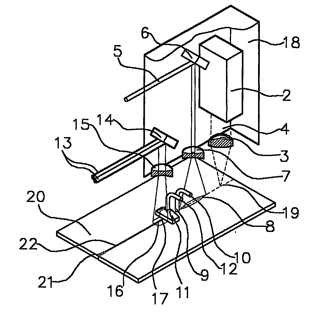
[0103] A fourth high frequency (266 μm, 10 kHz, 1.8 W) from an Nd:YV04 laser oscillator of Coherent Co. was collected by a convex lens and a focal point thereof was irradiated to an initiation end of an expected cutting line of a glass plate to the size of about 0.3 mm, to obtain the initial cracks.

[0104] A first carbon dioxide laser beam was irradiated while a pulse width of a pulse oscillator having an average output of 250 W of 10 kHz was controlled to 40% of a distance between centers of the pulse (hereinafter, referred to as ‘operation condition’, maximal 60%).

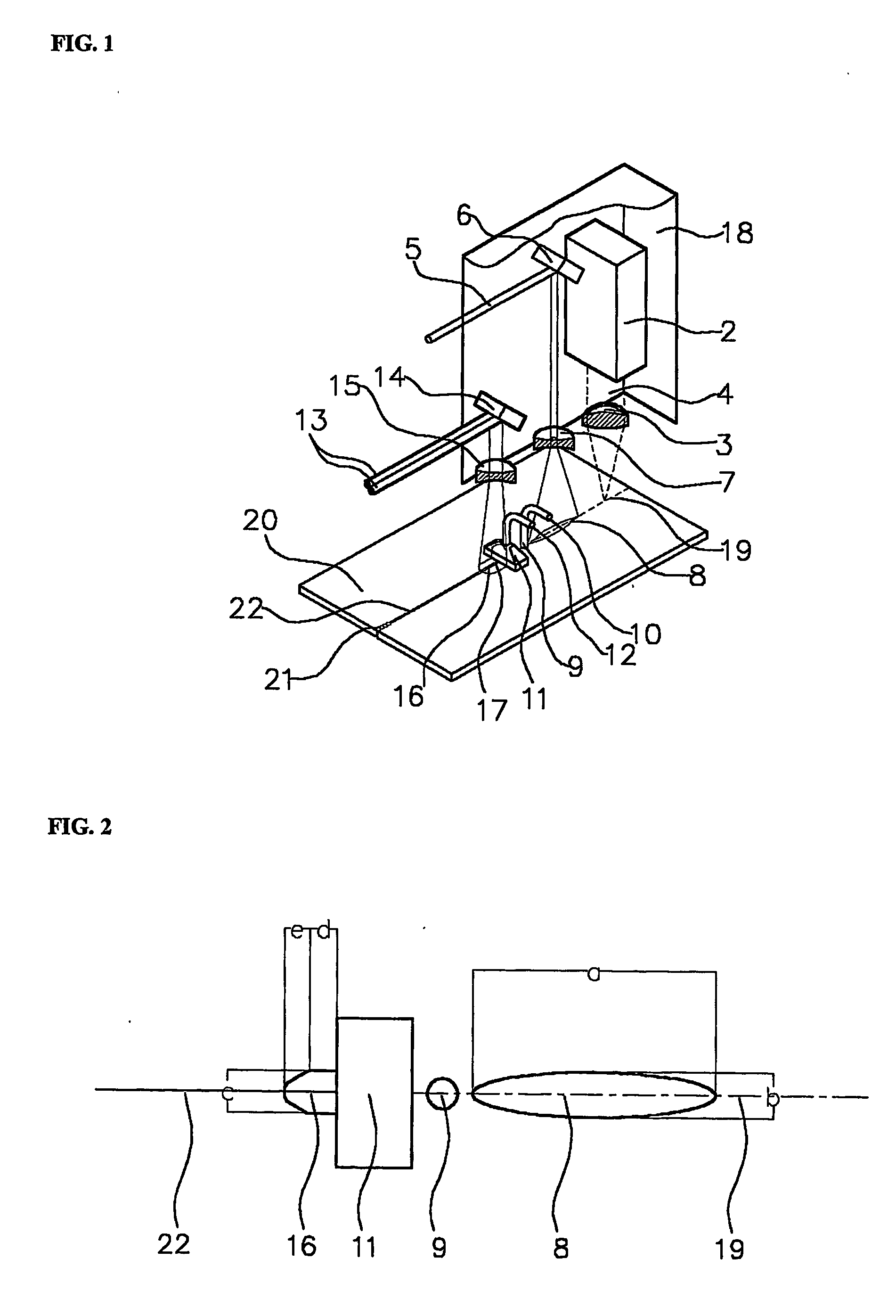
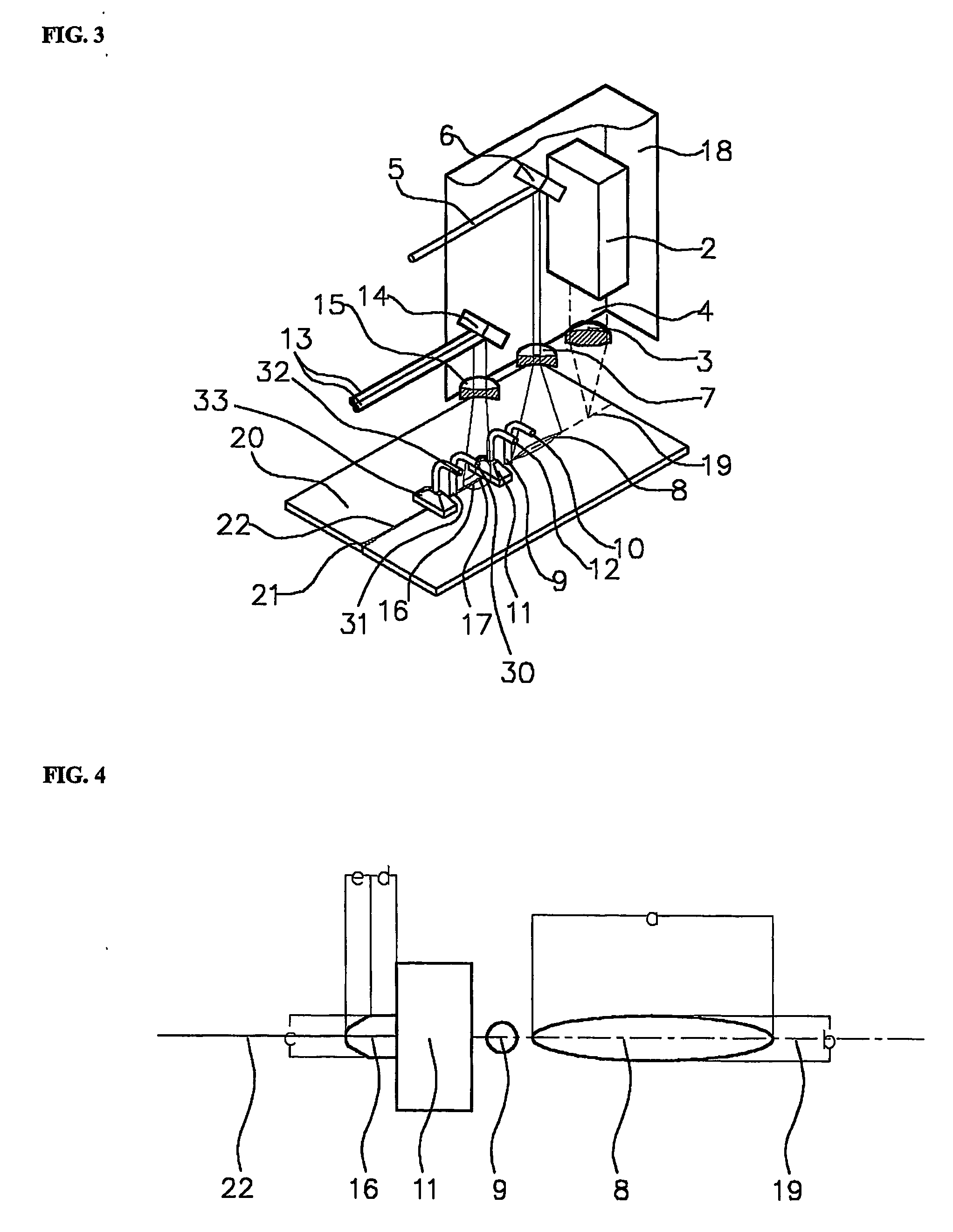
[0105] An irradiation area 141.6 mm2 of an oval shown in FIG. 3 was calculated by measuring ‘a’ as a long diameter and ‘b’ as a short diameter.

[0106] Then, water was pressurized under an air pressure of 3 kg / cm2 and sprayed in a haze state, to generate a scribe line.

[0107] A plane irradiation density in the oval was calculated to 0.386 joule / mm2, and the sc...

example 2

[0108] The present example was performed in the same manner as in Example 1, with the exception that the operation condition and the irradiation area of the first carbon dioxide laser beam were decreased to 13% and 59.2 mm2, respectively. As for the results, a scribe line with no problems was generated.

example 3

[0109] The present example was performed in the same manner as in Example 1, with the exception that the operation condition and the irradiation area were increased to 52% and 162.9 mm2, respectively, and the plane irradiation density was maintained at 0.442 joule / mm2. As for the results, a scribe line with no problems was generated.


PUM

PropertyMeasurementUnit
Fractionaaaaaaaaaa
Pressureaaaaaaaaaa
Lengthaaaaaaaaaa

Abstract

A glass plate cutting machine using a laser beam is provided to solve problems, such as uneven glass section and slanting cutting. By using the glass plate cutting machine of the current invention, the glass plate is irradiated with a first carbon dioxide laser beam of 0.05-2 joule/mm2 on a long oval shaped area of 20-200 mm2 according to an expected cutting line thereof, and immediately cooled with water, to generate a scribe line, which is then further irradiated with a second carbon dioxide laser beam of 0.1-0.5 joule/mm′ on the area of 20-200 mm2 thus obtaining a superior glass section.

Description

TECHNICAL FIELD [0001] The present invention relates to a machine for cutting a glass plate with a laser beam in fabrication of a display panel using liquid crystal, plasma and field emission, and a display panel fabricated by using the cutting machine. BACKGROUND ART [0002] Conventionally, a cutting method of a glass plate consists mainly of scribing the glass plate by means of an ultra-hard material, such as diamond, to generate a scribe line of the glass plate, which is then subjected to a breaking process under mechanical stress. [0003] Since Lumley has firstly reported a method of cutting a glass plate with a laser beam in Ceramic Bulletin, Vol. 48, No. 9, 1969, much research therefor has been performed and filed. [0004] According to the studies of Lumley, a glass material is not cut by heating, but cut by generating shallow cracks (hereinafter, referred to as ‘scribe line’) overheated and expanded by a laser beam and propagating them. Then, U.S. Pat. No. 3,932,726 discloses a ...

Claims


Application Information

Patent Timeline
IPC IPC(8): B23K26/38B28D5/00C03B33/09C03B33/10G02F1/1333
CPCC03B33/093G02F1/133351C03B33/102Y10T225/304Y10T225/307Y10T225/321C03B33/09
Inventor YOU, KI-YONGKIM, CHOON-TAEKAN, MIN-YOUNGKIM, MI-LEE
Owner RORZE SYST
Why Eureka
Try Eureka