Method for making a light weight high performance target

a high-performance, light-weight technology, applied in the direction of x-ray tube target materials, x-ray tube targets and convertors, manufacturing tools, etc., can solve the problems of excessive mass, limited parameters (target diameter and anode rotation speed), and limited anode materials of construction, so as to reduce the density of the anode, the effect of increasing the diameter of the anode and reducing the load on the anode bearing

Inactive Publication Date: 2006-07-13
GENERAL ELECTRIC CO
View PDF15 Cites 1 Cited by
  • Summary
  • Abstract
  • Description
  • Claims
  • Application Information

AI Technical Summary

Benefits of technology

[0010] One advantage of the invention is that an overall lower density of the anode is achievable. This enables the diameter of the anode to be increased without overloading the bearings. Additionally, the large diameter, lightweight target may operate in rotation speed ranges well in excess of conventional anodes because the anode has been designed to withstand the higher stress and strains caused by the loading. Furthermore, the chemistry of the graded CTE material layers reduces the propensity for undesirable formation, such as tungsten carbide formation, improving the anode's reliability over its life. Also, the target adherence and reliability over the x-ray tube life are enhanced by grading the slurry mixture layers with differing CTEs so that even a substrate having very low or a high CTE may still retain the refractory metal target intact.

Problems solved by technology

The current anode materials of construction limit the allowable load and instantaneous power that the anode may be subjected to.
Thus, the parameters (target diameter and anode rotation speed) are limited by excessive mass, e.g. formed from a solid target material, or unacceptable burst strength of the target material on the anode.
The excessive mass increases the load upon the anode bearings; therefore it is desirous to have lighter target material.
The solid target material adds a significant amount of weight to the anode, thus increasing the overall density of the anode.

Method used


Image

  • Method for making a light weight high performance target
  • Method for making a light weight high performance target
  • Method for making a light weight high performance target

Examples


Embodiment Construction

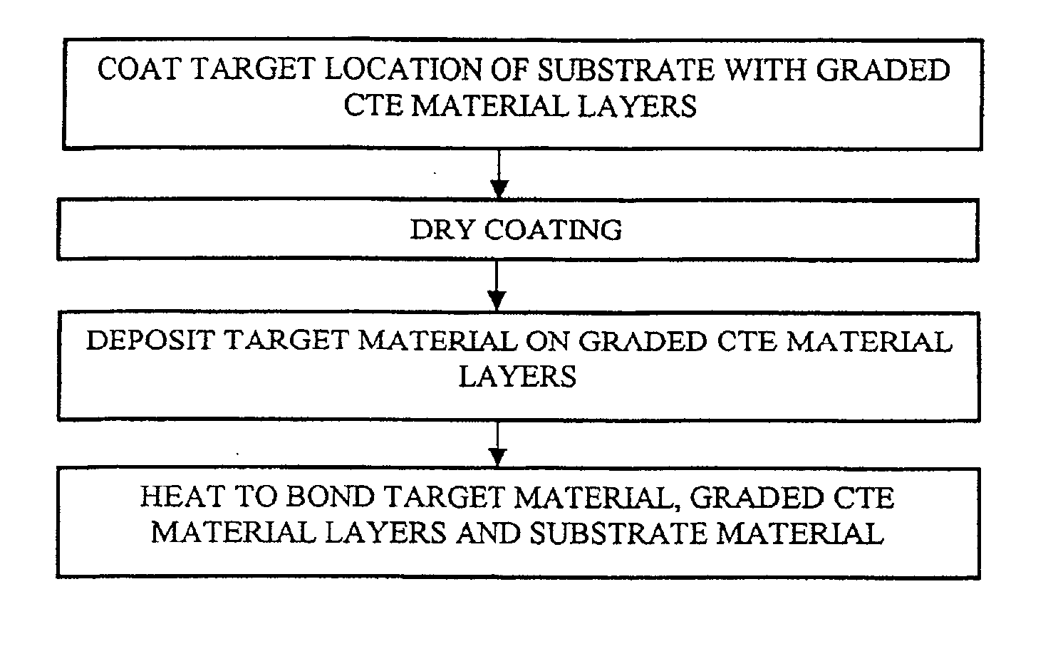
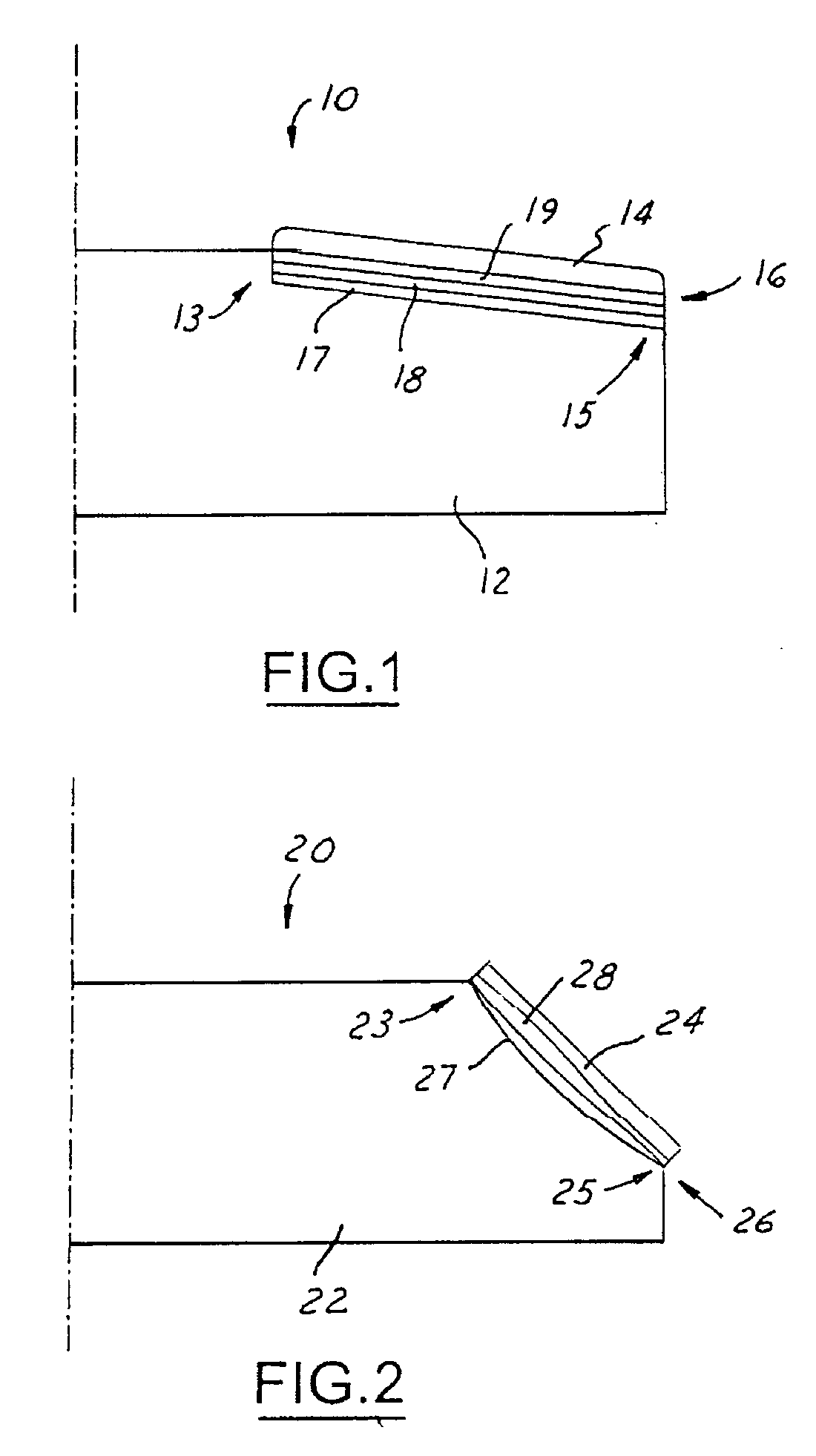
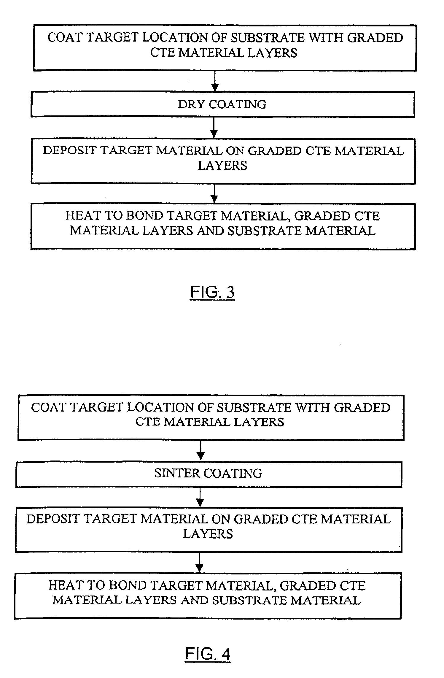
[0016] In the following figures the same reference numerals will be used to illustrate the same components in the various views. The present invention is described with respect to a computed tomography device. However, those skilled in the art will recognize that the present invention has several applications within the medical imaging field and outside the medical imaging field. That is, the present invention is suitable for applications that employ rotating x-ray anodes. The present invention is also suitable for applications that require a static x-ray anode having a substrate material with differing physical properties from the target material.

[0017] Referring now to FIG. 1, a partial cross-sectional view of an x-ray anode 10 is illustrated having a substrate material 12 and a target material 14 coupled together through one or more layers 16 of graded coefficient of thermal expansion (CTE) material. Although an x-ray anode 10 is illustrated, the present invention applies equall...


PUM

PropertyMeasurementUnit
particle sizeaaaaaaaaaa
temperatureaaaaaaaaaa

Abstract

An x-ray anode for use in an x-ray tube is provided. The x-ray anode includes a substrate material, a target material, and one or more graded coefficient of thermal expansion material layers. The target material is coupled to the one or more graded coefficient of thermal expansion material layers and the graded coefficient of thermal expansion material layers are coupled to the substrate material. A method of making the x-ray anode is also provided.

Description

RELATED APPLICATIONS [0001] This application is a divisional of pending U.S. patent application Ser. No. 10 / 709,042 filed on Apr. 8, 2004.TECHNICAL FIELD [0002] The present invention relates generally to an x-ray anode, and more particularly, to an x-ray anode having graded coefficient of thermal expansion material layers between the substrate and the target material. BACKGROUND DESCRIPTION [0003] There is a desire in the medical imaging industry to accommodate an increasing customer preference for shorter scan times in Computed tomography (CT) x- ray scanners. In order to accomplish the shorter scan times, the x-ray tube on the CT scanner is rotated around a gantry at increasing speeds and the instantaneous power of the x-ray tube directed at the target material on the anode must be increased to maintain X-ray flux. These two requirements require the target diameter on the anode to be maximized within the allowable design envelope and the anode rotation speed to be increased in ord...

Claims


Application Information

Patent Timeline
Patent Type & Authority Applications(United States)
IPC IPC(8): B23K31/02C23C14/00C25B9/00C25B11/00C25B13/00H01J35/06H01J35/08H01J35/10H01J35/12
CPCH01J35/06H01J2235/081H01J2235/088H01J35/10
Inventor TIEARNEY, THOMAS C. JR.LOUNSBERRY, BRIAN D.
Owner GENERAL ELECTRIC CO
Why Eureka
Try Eureka