Beam plasma source

a beam-type plasma source and beam-type technology, applied in the field of plasma and ion sources, can solve the problems of difficult linear extension of point electron source technologies such as filaments, heated low work function materials and hollow cathodes, and less effective in processing wide substrate applications, etc., to achieve the effect of producing uniform linear beams when utilizing large area substrates

Inactive Publication Date: 2006-07-13
GENERAL PLASMA
View PDF34 Cites 15 Cited by
  • Summary
  • Abstract
  • Description
  • Claims
  • Application Information

AI Technical Summary

Benefits of technology

[0017] Applicant's invention includes a plasma source. Applicant's plasma source includes a discharge cavity having a first width, where that discharge cavity includes a top portion, a wall portion, and a nozzle disposed on the top portio...

Problems solved by technology

While successfully applied to small substrate applications like semiconductors or optical filters, they are less effective in processing wide substrate applications.
This is primarily due to the use of point electron sources for beam creation and neutralization rather than uniform, linear electron sources....

Method used


Image

  • Beam plasma source
  • Beam plasma source
  • Beam plasma source

Examples


Embodiment Construction

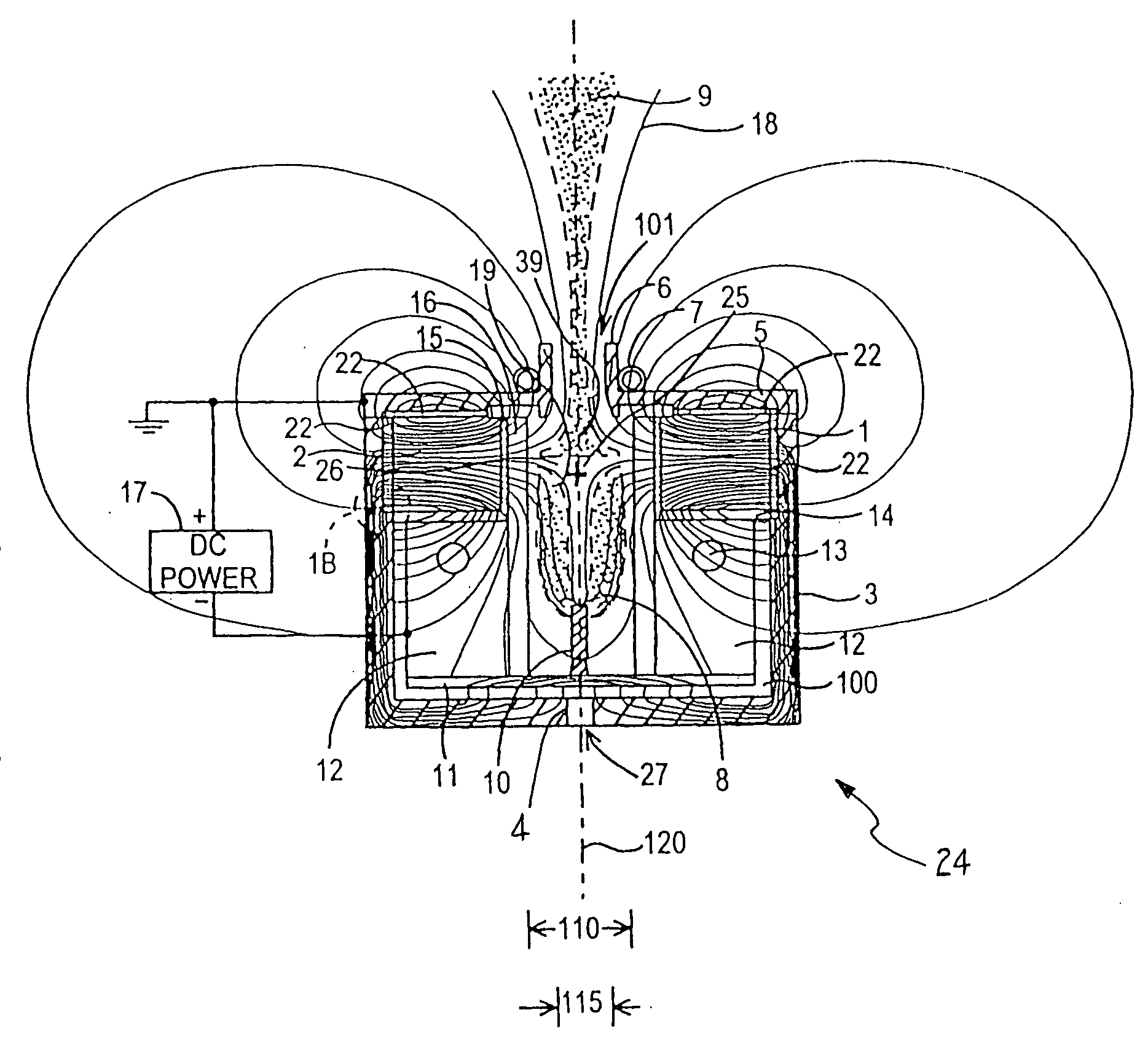
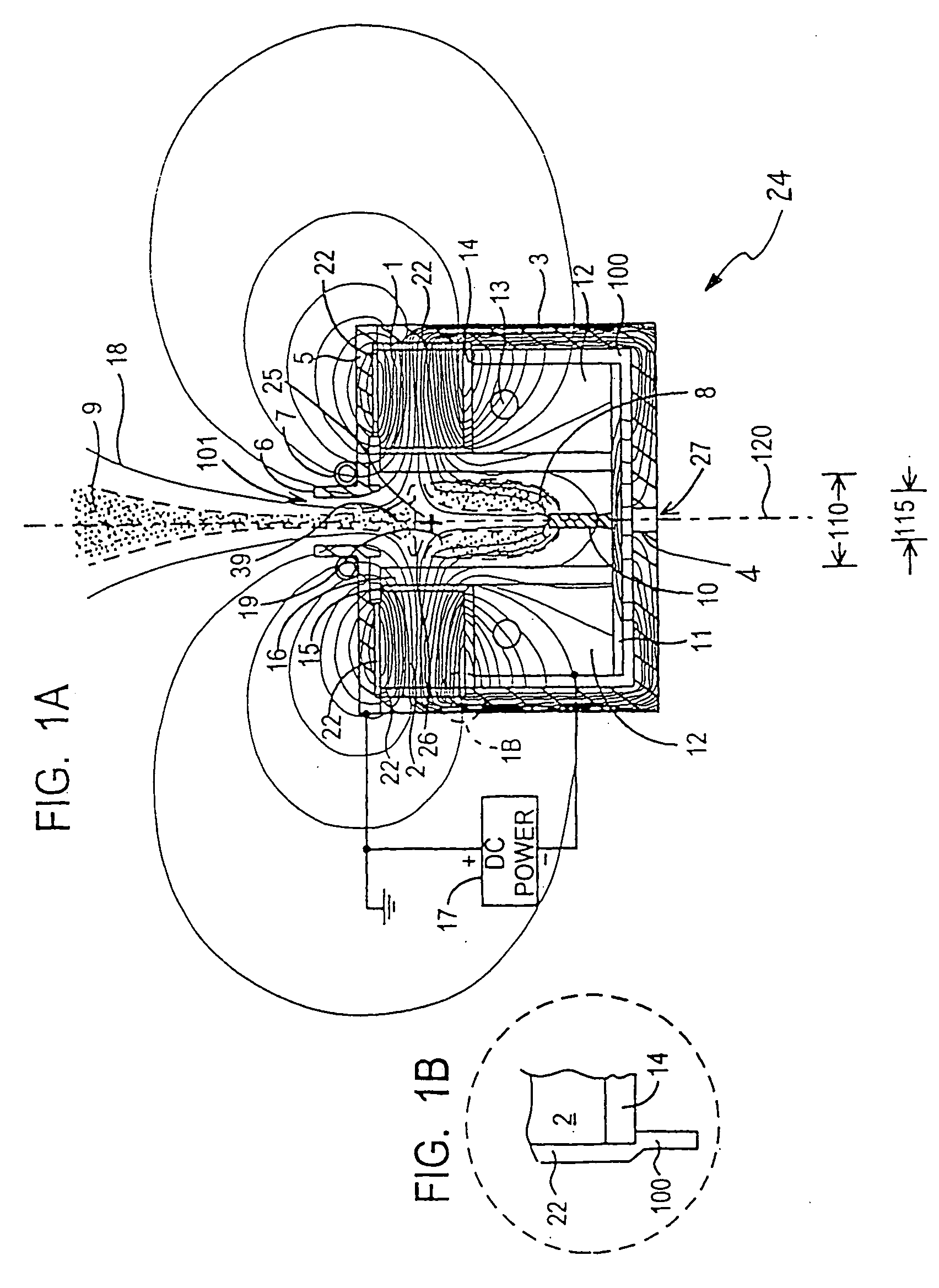
[0031]FIG. 1 shows a section view of beam source 24 producing a beam of dense plasma 9 projecting outwardly from nozzle 6. Aperture 101 extends through nozzle 6, into discharge cavity 26. Discharge cavity 26 has a first width 110. Aperture 101 has a second width 115, where the second width 115 is less than the first width 110. Center-line 120 comprises the middle of first width 110.

[0032] In certain embodiments, discharge cavity 26 comprises a parallelepiped having a rectangular cross section. In these embodiments, the first width 110 comprises the length of the longer side of that rectangular cross section. In certain embodiments, discharge cavity 26 a parallelepiped having a square cross section. In these embodiments, the first width 110 comprises the length of one side of that square cross section. In certain embodiments, discharge cavity 26 comprises a cylinder having a circular cross section. In these embodiments, the first width 110 comprises the diameter of that circular cro...


PUM

PropertyMeasurementUnit
Poweraaaaaaaaaa
Magnetic fieldaaaaaaaaaa
Widthaaaaaaaaaa

Abstract

A plasma source which includes a discharge cavity having a first width, where that discharge cavity includes a top portion, a wall portion, and a nozzle disposed on the top portion and extending outwardly therefrom, where the nozzle is formed to include an aperture extending through the top portion and into the discharge cavity, wherein the aperture has a second width, where the second width is less than the first width. The plasma source further includes a power supply, a conduit disposed in the discharge cavity for introducing an ionizable gas therein, and at least one cathode electrode connected to the power supply, where that cathode electrode is capable of supporting at least one magnetron discharge region within the discharge cavity. The plasma source further includes a plurality of magnets disposed adjacent the wall portion, where that plurality of magnets create a null magnetic field point within the discharge cavity.

Description

FIELD OF THE INVENTION [0001] The present invention relates to plasma and ion sources used for industrial processes such as plasma treatment, plasma enhanced chemical vapor deposition (PECVD) and plasma etching and to electric propulsion devices for space applications. BACKGROUND OF THE INVENTION [0002] Plasma and ion sources are usefully applied in a number of processes including: Plasma enhanced chemical vapor deposition (PECVD), reactive ion etching, plasma surface modification and cleaning, increasing the density of evaporated or sputtered films and assisting a reactive evaporation or sputtering process. Of growing interest is the application of these processes to larger substrates such as flexible webs, plasma televisions and architectural glass. [0003] Several plasma and ion sources are commercially available and many more have been disclosed. Commercially available plasma and ion sources include: Hollow cathode plasma sources, gridded ion sources, end hall ion sources, closed...

Claims


Application Information

Patent Timeline
IPC IPC(8): H01J7/24H01J37/32H05H1/48
CPCH01J27/146H01J37/32009H01J37/32357H05H1/48H01J2237/0815H05H1/46H01J37/3266
Inventor MADOCKS, JOHN E.
Owner GENERAL PLASMA
Why Eureka
Try Eureka