Frequency and phase control apparatus and maximum likelihood decoder
Active Publication Date: 2006-07-13
PANASONIC CORP
View PDF11 Cites 31 Cited by
Summary
Abstract
Description
Claims
Application Information
AI Technical Summary
This helps you quickly interpret patents by identifying the three key elements:
Problems solved by technology
Method used
Benefits of technology
[0033] According to a frequency and phase control apparatus of the present invention, a specific pattern length is detected based on the maximum likelihood decoding result both in a frequency and phase synchronous state and a frequency and phase asynchronous state. Therefore, the synchronization pattern length and the minimum pattern length can be detected more accurately than in the conventional art even when (i) the quality of the reproduction signal is poor, (ii) the distance between the data and the synchronization pattern is short, and (iii) the minimum pattern is provided immediately before or immediately after the synchronization pattern. Since the frequency error amount and the phase error amount can be detected with high precision, the reproduction cl
Problems solved by technology
Therefore, when the data is reproduced from the optical disc medium, the following inconvenience may occur.
In the case where the frequency of a clock component of the reproduction signal is significantly different from the frequency of a clock signal generated by a phase synchronization loop circuit, there is an undesirable possibility that the ph
Method used
Image
Click on the blue label to locate the original text in one second.
Reading with bidirectional positioning of images and text.
Examples
example 1
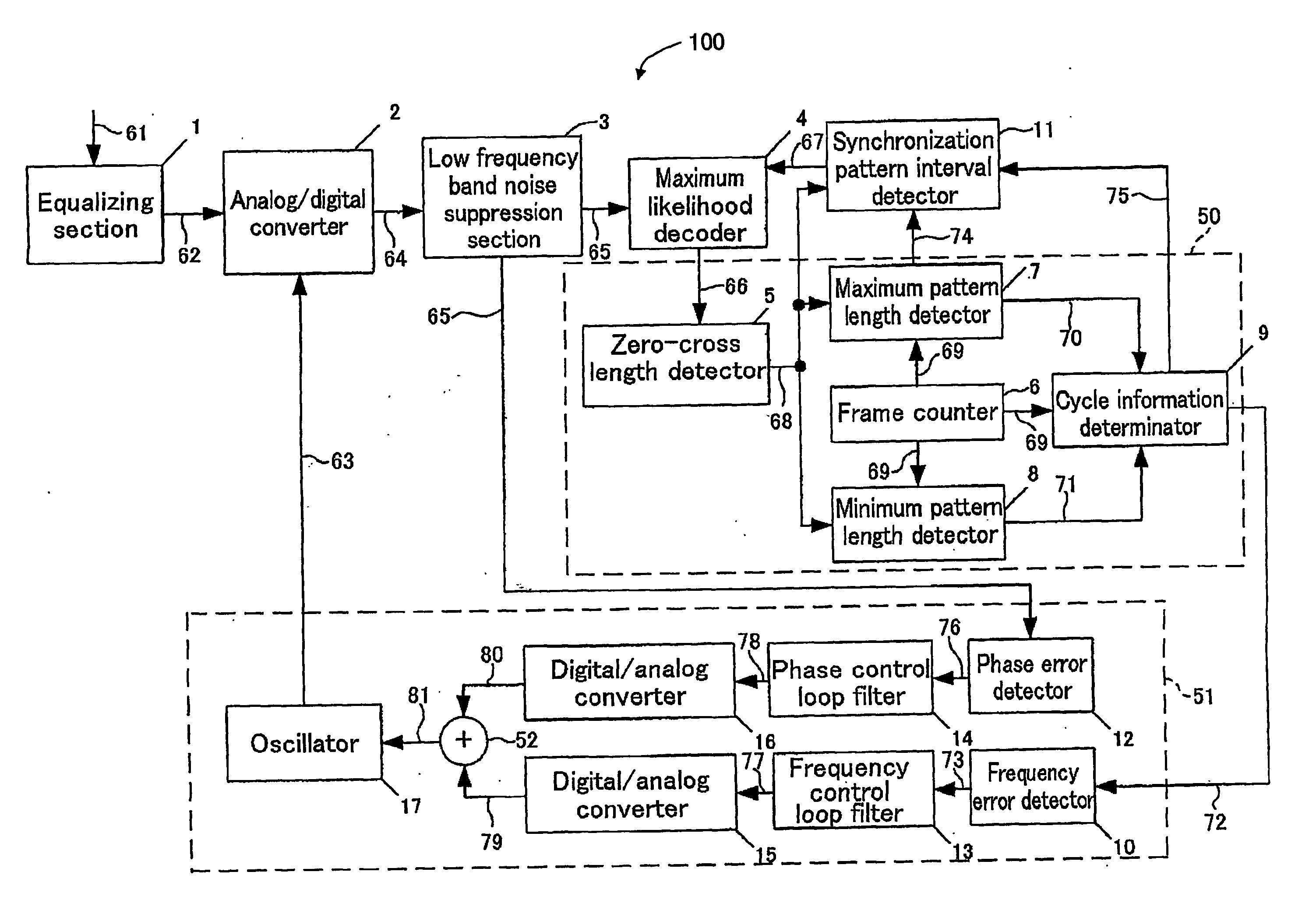
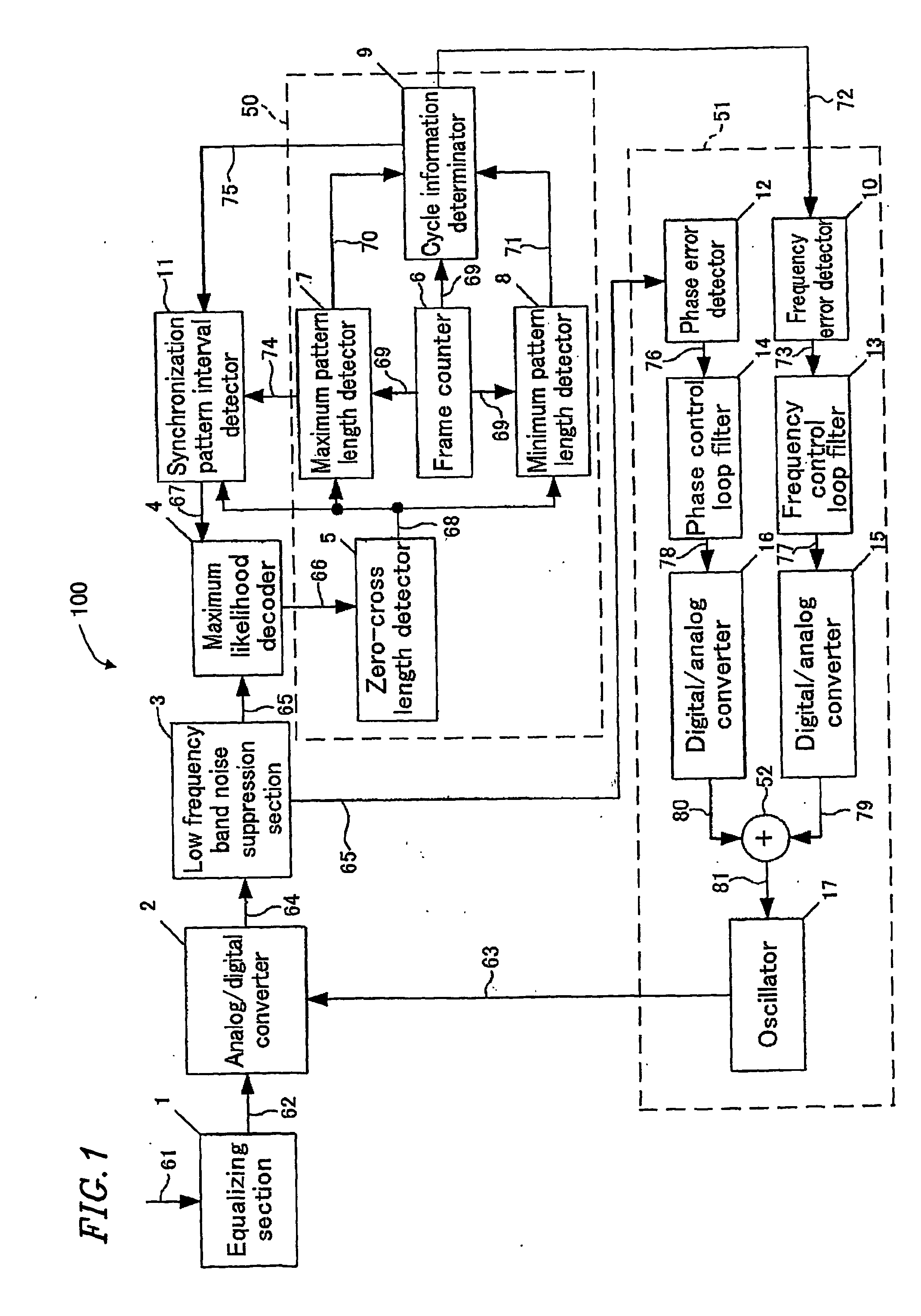
[0059]FIG. 1 is a block diagram illustrating a frequency and phase control apparatus 100 according to a first example of the present invention.
[0060] The frequency and phase control apparatus 100 includes a waveform equalizing section 1, an analog / digital converter 2, a low frequency band noise suppression section 3, a maximum likelihood decoder 4, a binary signal pattern detection section 50, a synchronization pattern interval detection section 11, and a clock generation section 51.
[0061] The binary signal pattern detection section 50 includes a zero-cross length detector 5, a frame counter 6, a maximum pattern length detector 7, a minimum pattern length detector 8, and a cycle information determinator 9. The clock generation section 51 includes a frequency error detector 10, a phase error detector 12, a frequency control loop filter 13, a phase control loop filter 14, digital / analog converters 15 and 16, an adder 52 and an oscillation section 17.
[0062] The waveform equalizing s...
example 2
[0121]FIG. 15 is a block diagram illustrating a frequency and phase control apparatus 200 according to a second example of the present invention.
[0122] The frequency and phase control apparatus 200 includes a waveform equalizing section 1, an analog / digital converter 2, a low frequency band noise suppression section 3, a maximum likelihood decoder 4, a first zero-cross length detection section 50a, a second zero-cross length detection section 50b, a frame counter 6, and a clock generation section 51a.
[0123] The first zero-cross length detection section 50a includes a first zero-cross length detector 5a and a maximum pattern length detector 7. The second zero-cross length detection section 50b includes a second zero-cross length detector 5b and a minimum pattern length detector 8. The clock generation section 51a includes a cycle information determinator 9, a frequency error detector 10, a phase error detector 12, a frequency control loop filter 13, a phase control loop filter 14, ...
PUM
Abstract
A frequency and phase control apparatus includes an analog/digital conversion section for converting a reproduction signal into a multiple bit digital signal based on a clock signal; a maximum likelihood decoding section for converting the multiple bit digital signal into a binary signal; a pattern detection section for detecting a pattern of the binary signal; and a determination section for determining whether or not the multiple bit digital signal and the clock signal are in synchronization with each other based on the detection result. When the determination result of the determination section indicates that the multiple bit digital signal and the clock signal are in synchronization with each other, the maximum likelihood decoding section generates a binary signal based on a first state transition rule; otherwise, the maximum likelihood decoding section generates a binary signal based on a second state transition rule.
Description
TECHNICAL FIELD [0001] The present invention relates to a frequency and phase control apparatus and a maximum likelihood decoder, and specifically to a frequency and phase control apparatus and a maximum likelihood decoder for realizing stable PLL (Phase-Locked Loop) phase synchronization for data reproduction based on a clock signal. BACKGROUND ART [0002] Digital data is often recorded on an optical disc medium using a system of uniformizing the linear velocity and thus uniformizing the recording density on the medium, as performed for a CD (Compact Disc), a DVD (Digital Versatile Disc) and the like. Data is recorded on the optical disc medium as being digitally modulated in the width of marks such that the linear recording density is uniform. Therefore, when the data is reproduced from the optical disc medium, the following inconvenience may occur. In the case where the frequency of a clock component of the reproduction signal is significantly different from the frequency of a clo...
Claims
Application Information
Patent Timeline
Application Date:The date an application was filed.
Publication Date:The date a patent or application was officially published.
First Publication Date:The earliest publication date of a patent with the same application number.
Issue Date:Publication date of the patent grant document.
PCT Entry Date:The Entry date of PCT National Phase.
Estimated Expiry Date:The statutory expiry date of a patent right according to the Patent Law, and it is the longest term of protection that the patent right can achieve without the termination of the patent right due to other reasons(Term extension factor has been taken into account ).
Invalid Date:Actual expiry date is based on effective date or publication date of legal transaction data of invalid patent.