Exothermic composition and exothermic element

a technology of applied in the field of exothermic composition and exothermic element, can solve the problems of inability to fully exploit the exothermic property, bad feeling in actual use, and inability to achieve full exothermic

Inactive Publication Date: 2006-07-13
MYCOAL PRODS CORP
View PDF11 Cites 68 Cited by
  • Summary
  • Abstract
  • Description
  • Claims
  • Application Information

AI Technical Summary

Benefits of technology

[0021] The present inventors have repeatedly conducted intensive studies for solving the above-mentioned problems and found that, when particle size of solid components and excessive water in a heat generating composition are made within appropriate ranges, he...

Problems solved by technology

However, although those powdery heat generating compositions have a good exothermic characteristic, their exothermic property is not able to be fully exploited because for example distribution of exothermic temperature is not constant due to uneven location of the heat generating composition, feeling in actual use is bad and manufacture of a heat generating body having a shape meeting the shape of a substance to be warmed is difficult because the composition is filled in a container bag having air permeability and used as a heat generating body.
Further, when a powdery heat generating composition is filled in a bag-shaped receiver to manufacture a heat generating body, the material is intermittently moved so that the heat generating composition is fallen down during the material is stopped whereby there is a problem that manufacturing speed becomes slow because stop and movement of the material are frequently repeated.
Incidentally, there is a product where uneven distribution of a heat generating composition is prevented utilizing the vacuum upon heat generation by a porous membrane but it has not been able to completely prevent the uneven distribution.
Further, although a higher speed than a method of filling of powder is possibly achieved in a method where a heat generating composition is fallen down together with a movement of a material at a constant speed as will be noted in the manufacture of a sheet-shaped heat generating body, it is necessary to disperse a powdery heat generating body in unwoven fabric which is a substrate material and there is a limit for the manufacturing speed.
There is a limit for the manufacture of heat generating bodies having various shapes as well.
On the other hand, in the case of a heat generating composition in a form of slurry, water content is high and maintenance of its shape is not possible as it is while, in the case of a viscous heat generating composition, fluidity is insufficient and it is not able to be direc...

Method used


Image

  • Exothermic composition and exothermic element
  • Exothermic composition and exothermic element
  • Exothermic composition and exothermic element

Examples


example 1

[0227] Water was added to a mixture of 100 parts by weight of iron powder (DKP manufactured by Dowa Teppun; particle size: not more than 250 μm), 8 parts by weight of active carbon (SA-Super manufactured by Norit; particle size: not more than 300 μm), 4 parts by weight of sodium chloride, 0.15 part by weight of water-absorptive polymer (KI-gel 201K manufactured by Kuraray; particle size: not more than 850 μm), 3.0 parts by weight of wood powder (particle size: not more than 300 μm) and 0.15 part by weight of calcium hydroxide (particle size: not more than 300 μm) followed by subjecting to further mixing to prepare a heat generating composition where water mobility value was 10.

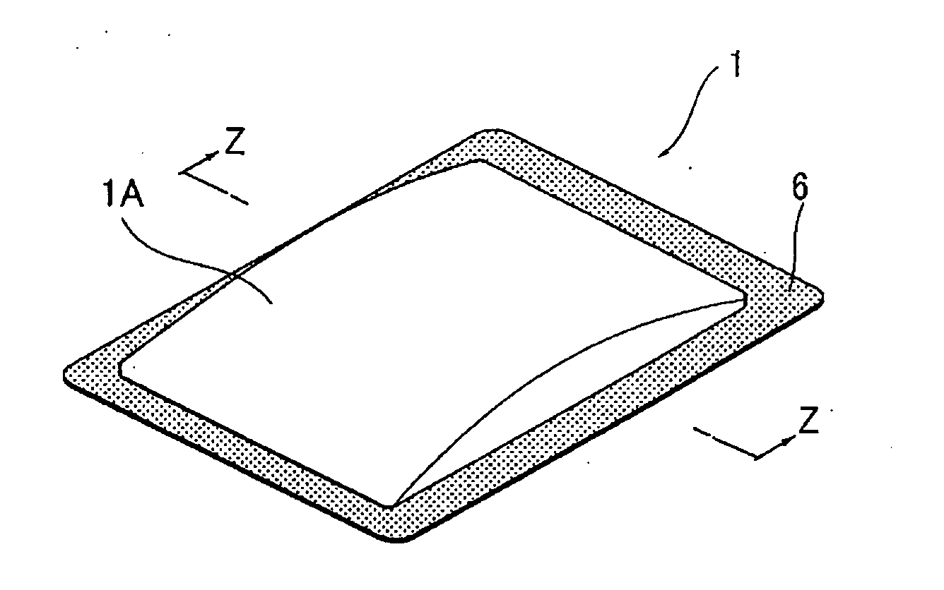
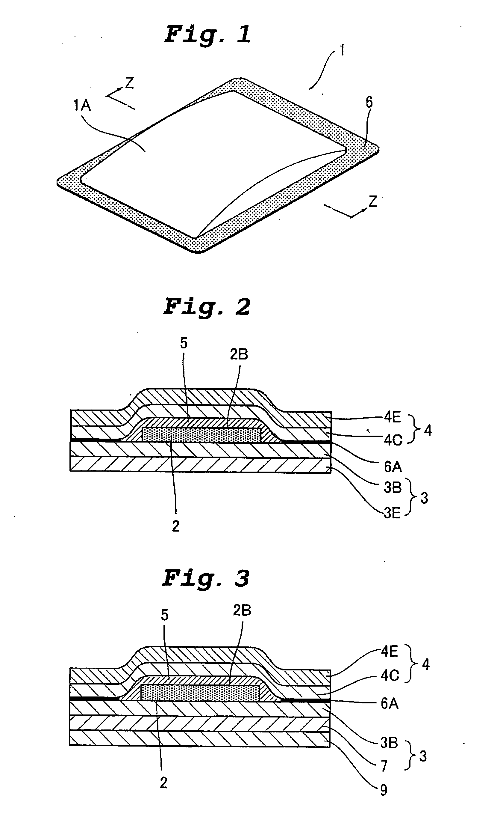
[0228] A non-gas-permeable packing material where polyethylene film 3B was laminated on nonwoven fabric 3E was named a substrate material 3 and, on the polyethylene film 3B, the heat generating composition 2 was layered by means of a molding passing through a die using a trimming die having trimming holes in ...

example 2

[0232] A non-gas-permeable and non-water-absorptive packing material where polyethylene film was laminated on a non-water-absorptive waterproof paper was used as a substrate material and the heat generating composition prepared in Example 1 was layered on the resulting water-proof paper by a molding by passing through a die using a trimming die whereupon a layered heat generating composition product was prepared. Further, a hot melt type pressure-sensitive adhesive was formed thereon by a melt blow method then, using a gas-permeable packing material where nonwoven fabric made of nylon, kraft paper and porous polyethylene film were layered in that order, layering was conducted in such a manner that the surface of the waterproof paper and the surface of the porous polyethylene film were contacted each other and the surroundings were adhered with compression and cut to prepare a rectangular flat heat generating body having 135 mm length, 100 mm width and 8 mm seal width.

[0233] Gas per...

example 3

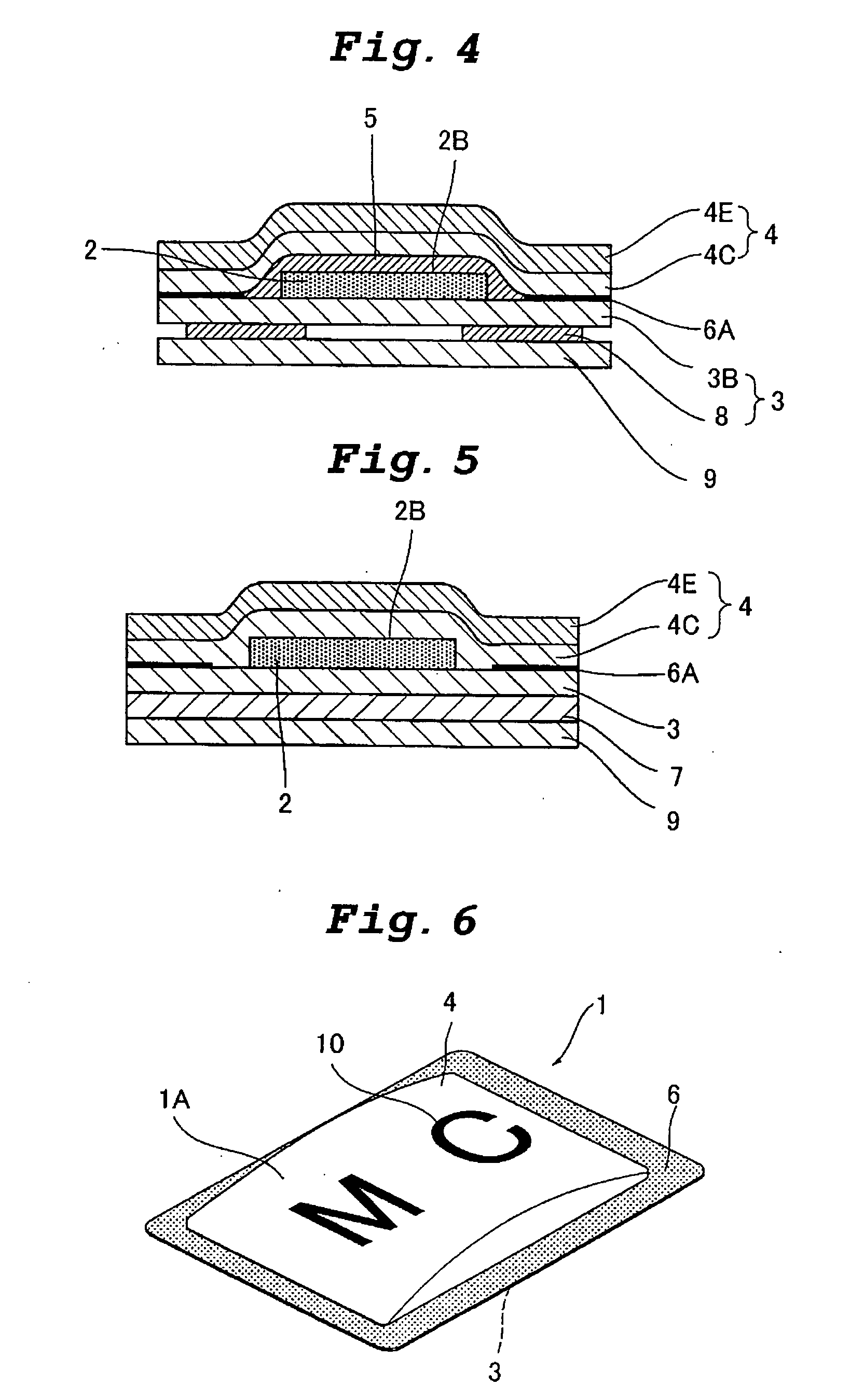
[0241] As shown in FIG. 3, a substrate material 3 where an acrylate pressure-sensitive adhesive layer 7 was formed on polyethylene film 3B was used instead of the substrate material 3 of Example 1 and the same operation as in Example 1 was conducted to prepare a heat generating body having 135 mm length, 100 mm width and 8 mm seal width. Incidentally, 9 in the drawing shows a releasing film.


PUM


Abstract

In a heat generating composition which generates heat by contacting with air, a heat generating composition which is characterized in that an exothermic substance, a reaction promoter, water and a carbon component are essential components, water mobility value thereof is 20 or less, maximum particle size of water-insoluble solid components excluding the reaction promoter and water is 1 mm or less where 80% or more thereof has a particles size of 300 μm or less, water in the heat generating composition does not function as a barrier layer and exothermic reaction takes place when contacted to the air. A heat generating composition having a molding property and a shape-holding property and also having an exothermic characteristic whereby exothermic reaction is able to start by contacting to the air immediately after the molding and a heat generating body using the same are provided.

Description

TECHNICAL FIELD [0001] The present invention relates to a heat generating composition having an exothermic characteristic having a molding property and a shape-holding property and being able to start in exothermic reaction soon after contacting to air after molding and also to a heat generating body using the same. BACKGROUND ART [0002] Heat generating compositions utilizing an oxidation reaction of metal such as iron have been provided as powdery, viscous and creamy substances. Heat generating bodies utilizing the same are very excellent in view of cost, safety, exothermic temperature, etc. and, for example, they have been already practically used as the so-called chemical warmers for human body being packed in a bag having gas permeability. [0003] Seeking the prevention of uneven distribution of heat generating composition and the fitting property by means of various shapes for achieving more comfortable feeling in use, various heat generating compositions for attempting a shape ...

Claims


Application Information

Patent Timeline
IPC IPC(8): B31B45/00A61L15/44A61F7/03A61F7/08C09K5/18F24V30/00
CPCA61F7/034A61N2005/066Y10T428/13F24J1/00C09K5/18F24V30/00C09K5/16
Inventor USUI, KAORUKIMURA, HISAOAIDA, MICHIODODO, TOSHIHIRO
Owner MYCOAL PRODS CORP
Why Eureka
Try Eureka