Ag base alloy thin film and sputtering target for forming Ag base alloy thin film

a technology thin film, which is applied in the field of ag alloy films, can solve the problems of low abrasion resistance of ag film, no ag base alloy has been found which satisfies all these requirements, and the durability of ag film is not as high as that of ag base alloy, etc., to achieve high thermal conductivity/high reflectance/high durability, enhance recording and reproduction characteristics, and improve the reliability of optical information

Inactive Publication Date: 2006-07-13
KOBE STEEL LTD
View PDF60 Cites 23 Cited by
  • Summary
  • Abstract
  • Description
  • Claims
  • Application Information

AI Technical Summary

Benefits of technology

[0029] In view of the foregoing circumstances, the present invention has been completed. It is therefore a first object of the present invention to provide an Ag base alloy reflective film or semi-transmissive reflective film for an optical information recording medium having high reliability as use for a high-speed DVD or a next-generation optical disk, and an optical information recording medium including the reflective film or the semi-transmissive reflective film by finding an Ag base alloy having higher thermal conductivity / higher reflectance / higher durability than those of pure Ag or conventional Ag alloys.
[0030] It is a second object of the present invention to provide an electromagnetic-shielding Ag alloy film which is less likely to undergo aggregation of Ag, and therefore has excellent durability, and an electromagnetic-shielding Ag alloy film-formed product.
[0031] It is a third object of the present invention to provide a high-performance optical reflective film having high optical reflectance almost equal to the high optical reflectance inherent in Ag, and a liquid crystal display device using the optical reflective film by finding an Ag base alloy capable of preventing the growth of crystal grains of Ag and the aggregation of Ag atoms as much as possible.

Problems solved by technology

However, it is superior to an Al-based reflective film in terms of durability, but it does not have durability as high as that of the Au-based reflective film.
However, no Ag base alloy has been yet found which satisfies all these requirements.
However, the Ag film has low abrasion resistance, and further, it has insufficient durability against environment.
Therefore, it will be deteriorated due to moisture or the like, and hence it is difficult to use for a long period.
However, a sufficient solution has not yet been made from the viewpoints of abrasion resistance and durability improvements.
Eventually, the Ag film will be deteriorated with the passage of time, so that the pure Ag film lacks the practicality.
However, the visible light transmittance is decreased, so that it becomes dark in the room.
However, even if Ag is coated with a transparent dielectric film, Ag aggregates from the defective portions such as pinholes and scratches of the transparent dielectric film itself as the starting points when exposed to air.
As a result, the Ag film tends to undergo film breaking (i.e., break in the continuity of the film), so that film breaking occurs (the continuity of the film is broken).
Further, unlimited number of white points occur due to the aggregation on the Ag film-applied substrate surface of glass, film, or the like, resulting in reductions of designability and salability.
Even with the proposals or the proposed Ag alloy films, the aggregation of Ag proceeds with passage of time, resulting in deterioration of the Ag alloy films.
Therefore, the result is that the film must be processed into a laminated glass or an insulating glass for use so that the Ag alloy film surface is not exposed to air, leading to an increase in manufacturing cost.
This results in a loss of the value in use as a commercially available product.
Further, even in the case where it has been processed into a laminated glass or an insulating glass, the resulting glass does not have sufficient durability because long-term use results in deterioration of the Ag alloy film.
However, in the case where the Ag thin film has been exposed into air for a long time under high temperatures during manufacturing of a liquid crystal display device, in the case where it has been exposed under high temperatures and high humidities for a long time during use after manufacturing, or in other cases, white turbidity and white points caused by the increase in size of crystal grains, the aggregation of Ag atoms, the oxidation of Ag, or the like occur, resulting in a decrease in reflectance.
For this reason, it has not been possible to obtain a high reflectance inherent in Ag.
Further, the inevitable heat history (to 200° C.) during device manufacturing causes the crystal grain growth and the aggregation of Ag atoms, which involve the increase in roughness of the thin film surface and the anomalous grain growth.
This results in a difficulty in device formation, and a further reduction in reflectance.
However, even with the forgoing prior-art techniques, it has not been possible to sufficiently suppress the growth of crystal grains of Ag and the aggregation of Ag atoms.
Accordingly, it has not been possible to ensure high optical reflectance inherent in Ag.

Method used


Image

  • Ag base alloy thin film and sputtering target for forming Ag base alloy thin film
  • Ag base alloy thin film and sputtering target for forming Ag base alloy thin film
  • Ag base alloy thin film and sputtering target for forming Ag base alloy thin film

Examples


example 1

[0147] First, the measurement and evaluation method of each characteristic will be described below.

[0148] [Manufacturing of Ag Base Alloy Thin Film]

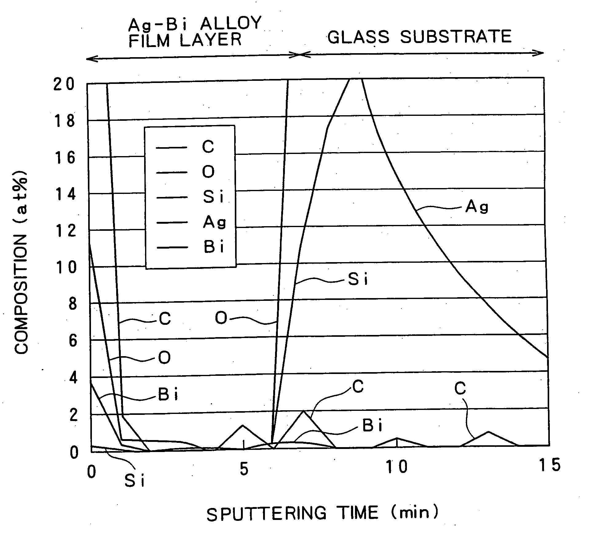
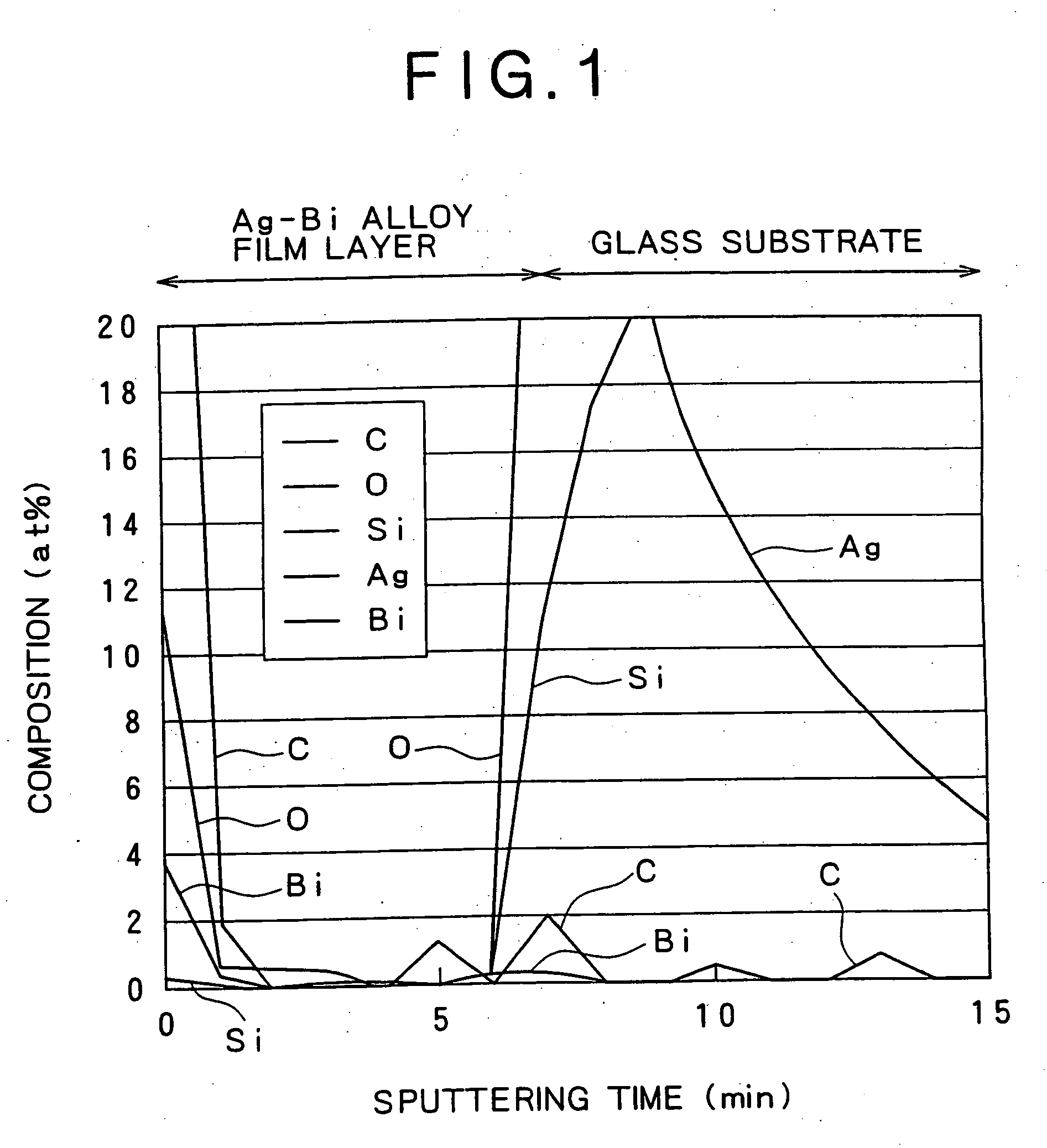
[0149] Using composite targets each formed by locating chips of various additive elements on a pure Ag sputtering target, each thin film of pure Ag (sample No. 1), Ag—Bi alloys (sample Nos. 2to5), Ag—Sb alloys (sample Nos. 6-9), Ag—Bi—Nd alloys (sample Nos. 10 to 14), Ag—Bi—Y alloys (sample Nos. 15-19), Ag—Sb—Nd alloys (sample Nos. 20 to 24), Ag—Sb—Y alloys (sample Nos. 25 to 29), Ag—Bi—Cu alloys (sample Nos. 30 to 34), Ag—Bi—Au alloys (sample Nos. 35 to 39), Ag—Sb—Cu alloys (sample Nos. 40 to 44), Ag—Sb—Au alloys (sample Nos. 45to49), Ag—Bi—Nd—Cu alloy (sample No. 50), Ag—Bi—Nd—Au alloy (sample No. 51), Ag—Bi—Y—Cu alloy (sample No. 52), Ag—Bi—Y—Au alloy (sample No. 53), Ag—Sb—Nd—Cu alloy (sample No. 54), Ag—Sb—Nd—Au alloy (sample No. 55), Ag—Sb—Y—Cu alloy (sample No. 56), Ag—Sb—Y—Au alloy (sample No. 57), Ag—Si alloy (sample No. 58), a...

example 1-1

Measurement of Thermal Conductivity

[0151] The thermal conductivity of each thin film with a thickness of 100 nm manufactured as described above was measured in the following manner. The sheet resistance Rs was measured with a four probe method by means of 3226-mΩ Hi TESTER manufactured by HIOKI Co, and the film thickness t was measured by means of alpha-step 250 manufactured by TENCOR INSTRUMENTS Co. Then, the electrical resistivity ρ(=sheet resistance Rs×film thickness t) was calculated, and then, the thermal conductivity κ(=2.51×absolute temperature T / electrical resistivity ρp) at an absolute temperature of 300 K (≈27° C.) was calculated by the law of Wiedemann-Franz. Incidentally, for the evaluation, the one showing 256 W / (m·K) or more, which corresponds to 80 percent or more of the thermal conductivity: 320 W / (m·K) of a pure Ag thin film has been judged as having high thermal conductivity. The results are shown in Tables 1 and 2.

[0152] As apparent from Tables 1 and 2, any of t...

example 1-2

Measurement of Reflectance

[0153] The reflectance with respect to a visible light (wavelength: 400 to 800 nm) of each thin film with a thickness of 100 nm manufactured in the foregoing manner was measured by means of Polar Kerr Scope NEO ARK MODEL BH-810 manufactured by Nihon Kagaku Engineering Co. Incidentally, for the evaluation of high reflectance, the one showing 80% or more (wavelength 405 nm) and 88% or more (wavelength 650 nm) relative to 90.8% (wavelength 405 nm) and 92.5% (wavelength 650 nm), respectively, which are the reflectances of the pure Ag thin film has been judged as having a high reflectance. Herein, the wavelength of 405 nm is the wavelength of a laser light to be used for a next-generation optical disk, and the wavelength of 650 nm is the wavelength of a laser light to be used for a DVD. The results are shown in Tables 3 and 4.

[0154] As apparent from Tables 3 and 4, any of the pure Ag thin film (sample No. 1), the thin films of the Ag—Si alloy (sample No. 58) a...


PUM

PropertyMeasurementUnit
thicknessaaaaaaaaaa
thicknessesaaaaaaaaaa

Abstract

The present invention relates to an Ag alloy film. Particularly, it is preferably used as a reflective film or semi-transmissive reflective film for an optical information recording medium having high thermal conductivity / high reflectance / high durability in the field of optical information recording media, an electromagnetic-shielding film excellent in Ag aggregation resistance, and an optical reflective film on the back of a reflection type liquid crystal display device, or the like. The Ag alloy film of the present invention comprises an Ag base alloy containing Bi and / or Sb in a total amount of 0.005 to 10% (in terms of at %). Further, the present invention relates to a sputtering target used for the deposition of such an Ag alloy film.

Description

CONTINUATION DATA [0001] This application is a Continuation of prior U.S. application Ser. No. 10 / 633,550, filed on Aug. 5, 2003, pending.BACKGROUND OF THE INVENTION [0002] 1. Field of the Invention [0003] The present invention relates to an Ag alloy film. More particularly, it relates to an Ag alloy film preferably used as a reflective film or a semi-transmissive reflective film for an optical information recording medium having high thermal conductivity / high reflectance / high durability in the field of optical information recording media, an electromagnetic-shielding film excellent in Ag aggregation resistance, or an optical reflective film on the back of a reflection type liquid crystal display device or the like. Further, the present invention relates to a sputtering target for use in deposition of such an Ag alloy film. [0004] 2. Description of the Related Art [0005] For the reflective films or the semi-transmissive reflective films included in optical information recording medi...

Claims


Application Information

Patent Timeline
Patent Type & Authority Applications(United States)
IPC IPC(8): C22C5/06B32B15/04C22C5/08C23C14/14C23C14/18C23C14/34G11B7/24G11B7/253G11B7/2531G11B7/257G11B7/258G11B7/259G11B7/26
CPCC22C1/002Y10T428/1095C22C5/08C23C14/024C23C14/185C23C14/205C23C14/3414C23C14/584G02B5/0808G11B7/252G11B7/2531G11B7/257G11B7/258G11B7/259G11B7/266Y10T428/12924Y10T428/12431Y10T428/21Y10T428/10Y10T428/265Y10T428/12896Y10T428/1059C22C5/06Y10T428/31678Y10T428/12C09K2323/05C09K2323/061C09K2323/00C22C1/11B63H25/38
Inventor TAUCHI, YUUKITAKAGI, KATSUTOSHINAKAI, JUNICHISATO, TOSHIKI
Owner KOBE STEEL LTD
Why Eureka
Try Eureka