Method and device for local ventilation by buiding airflow and separating airflow

Inactive Publication Date: 2006-07-13
HIDEO NISHIMURA
View PDF4 Cites 27 Cited by
  • Summary
  • Abstract
  • Description
  • Claims
  • Application Information

AI Technical Summary

Benefits of technology

[0046] By completing ventilation locally by discharge, the ventilation rate and air conditioning capacity can be saved, and by keeping low the capacity of ventilation and air conditioning equipment, the initial cost and running costs of the ventilation and air conditioning equipment can be saved, and by reduction of consumption of electric energy, generation of global warming gases can be cut low.
[0047] As a result of substantial reduction of ventilation rate and air conditioning capacity, a sufficient allowance is made in the existing power source capacity and air conditioning capacity, and the existing ducts and other v

Problems solved by technology

However, such conventional overall ventilation method has the following problems, and it has been desired to solve them.
As represented by kitchen, when the overall ventilation system is installed in a room having many sources of contaminants, the ventilation rate is enormous and discharge efficiency is poor in ventilation, and since a huge volume of fresh air is introduced as intake, the indoor air becomes same as outdoor air.
Discharge by suction and discharge stream by using mechanical power is poor in controllability, and only the contaminants cannot be discharged effectively, and heat, steam, oil fuse, odor or vapor may be stagnant in the room, and the indoor air conditioning state is poor.
Increase of ventilation air flow and air conditioning capacity leads to increase of ventilation and air conditioning equipment capacity, and also increase in initial cost and running cost of ventilation and air conditioning equipment.
In addition, increase of ventilation and air conditioning equipment capacity also leads to increase of electric capacity of equipment, and

Method used


Image

  • Method and device for local ventilation by buiding airflow and separating airflow
  • Method and device for local ventilation by buiding airflow and separating airflow
  • Method and device for local ventilation by buiding airflow and separating airflow

Examples


embodiment 1

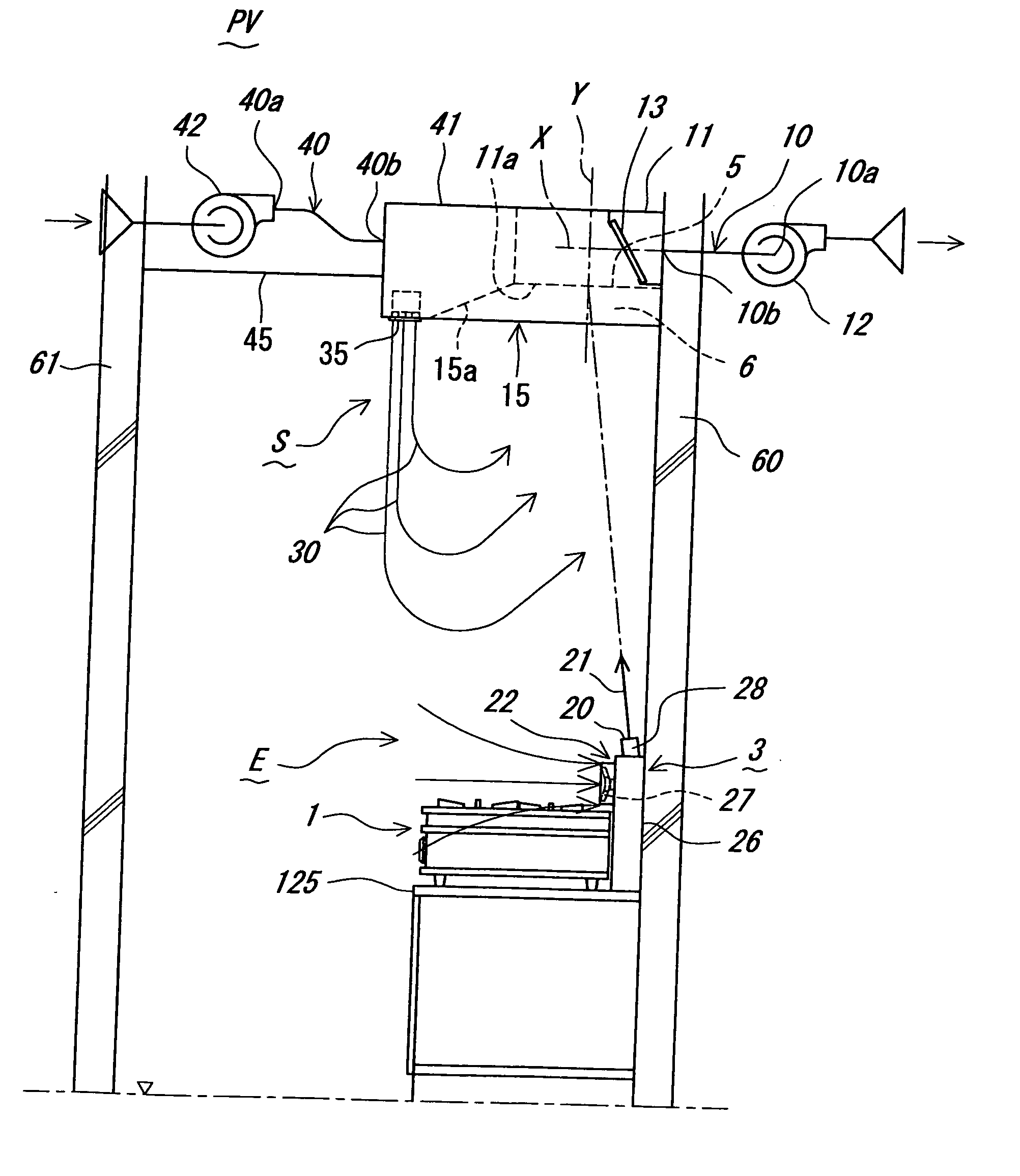
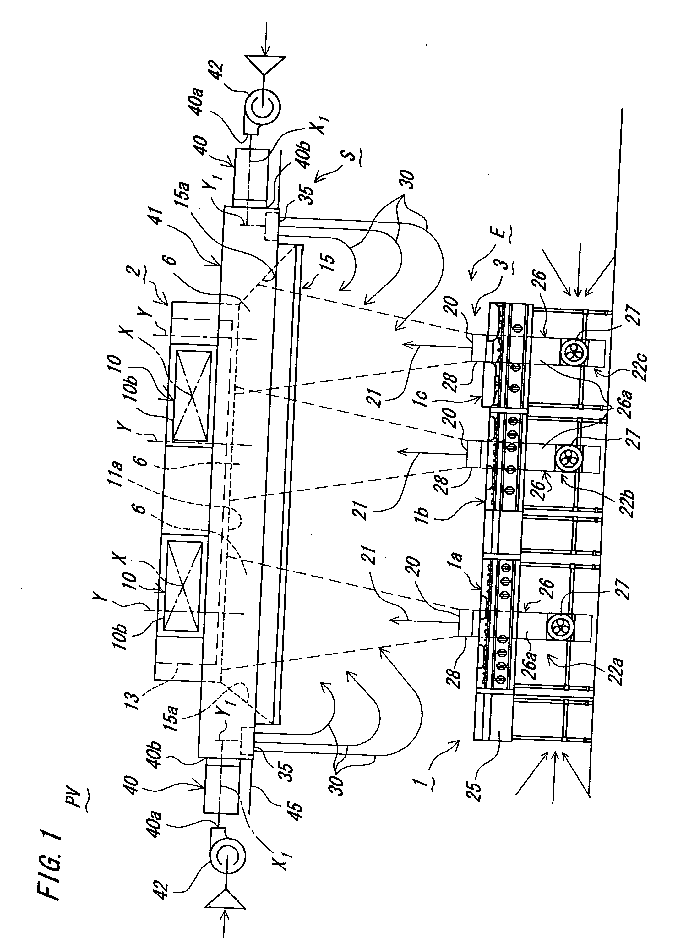
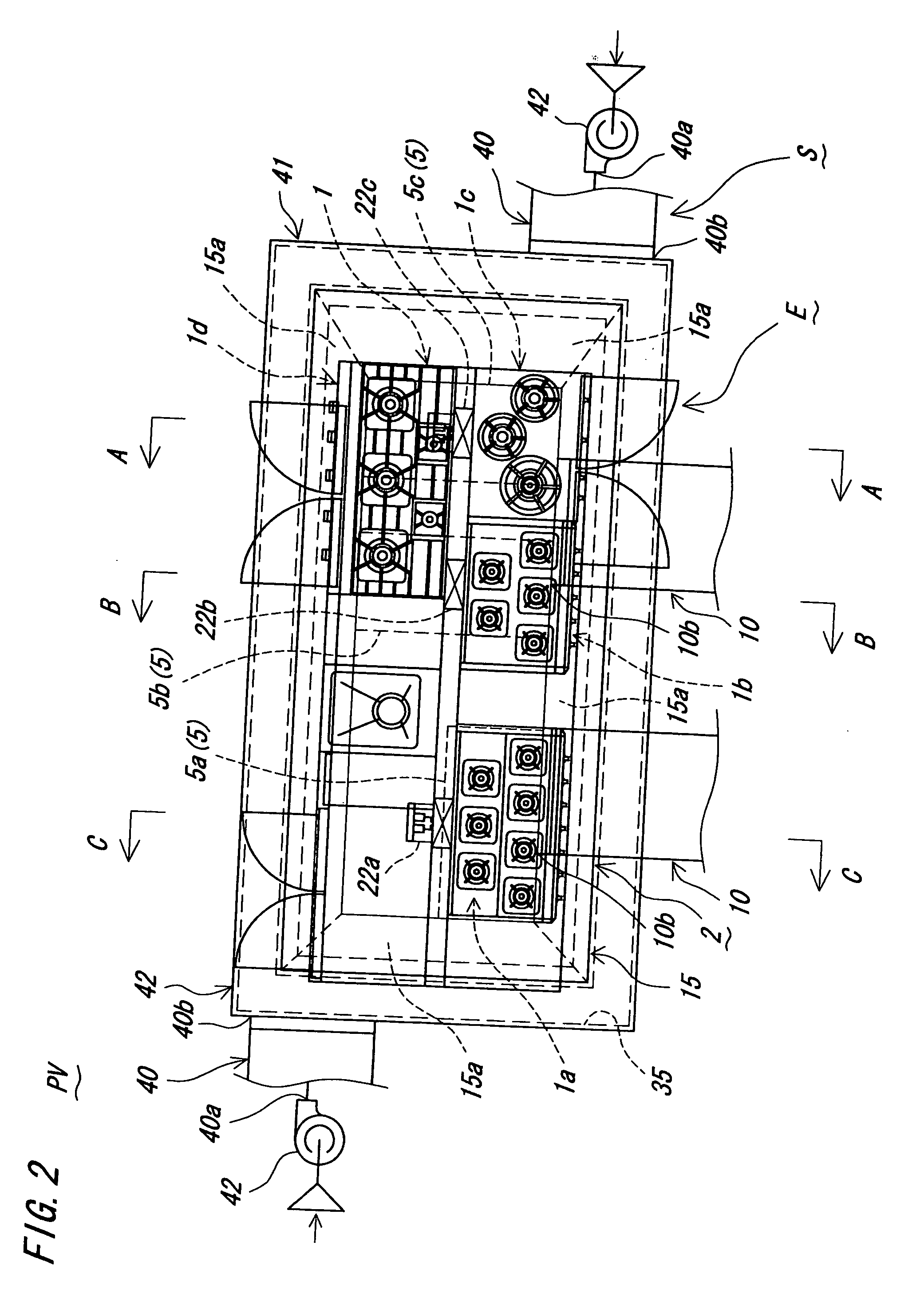
[0073] A local ventilator of the invention is shown in FIG. 1 and FIG. 2. The local ventilator PV is an apparatus for ventilating locally around the contaminant source in a room having a contaminant source to cause polluted air, and specifically it is for a professional kitchen use in a school, hospital or relatively large building in a room depending specific habitability and working efficiency.

[0074] The local ventilator PV has a discharger E for combustion heating type cooking device 1 such as table cooking range as source of contaminant, and intake device (intake means) S is integrally provided in the discharger E.

[0075] The discharger E mainly consists of suction discharge stream generator (suction discharge stream generating means) 2, and blow induction stream generator (blow induction stream generating means) 3.

[0076] The suction discharge stream generator 2 has a suction opening 5 provided above the cooking device 1, and is designed to generate an upward suction discharge...

embodiment 2

[0130] This preferred embodiment is shown in FIG. 7, and it is a modification of blow induction stream generator 3 in embodiment 1.

[0131] That is, an induction stream generating device 122 of the induction stream generator 3 of the preferred embodiment is suspended from the discharge hood 15 by suspending means 54 such as SUS chain, and the upper part of the device main body 26 of cylindrical shape functioning also as straightening part is blow nozzle 28 having a blow opening 20, and a blow fan 27 as induction stream source is vertically provided concentrically in the lower part of the device main body 26, and its air source is indoor air.

[0132] The blow nozzle 28 is vertical and upright so that its axial line may pass nearly the center of the suction opening 5 of the discharge box 11 of the suction discharge stream generator 2, and the blow induction stream 21 is blown out vertically upward toward the inside of the suction opening 5 from the blow opening 20.

[0133] Other structur...

embodiment 3

[0134] This preferred embodiment is shown in FIG. 8, and it is a modification of blow induction stream generator 3 in embodiment 1.

[0135] That is, in the induction stream generator 3 of the preferred embodiment, the induction stream generating device 122 of embodiment 2 is an independent self-supporting type, disposed upright at the side of the cooking range stand 125 of the combustion heating type cooking device 1 by means of supporting leg 123.

[0136] Other structure and action are same as in embodiment 1.


PUM


Abstract

To present technology of discharge and local ventilation capable of decreasing ventilation capacity and air conditioning capacity substantially by lowering the air conditioning load by introduction of fresh air by intake, and decreasing the capacity of air conditioning and ventilation facilities by eliminating consumption of electrical energy.
This a method of discharging polluted air near combustion heating type cooking device (1) in a room having combustion heating type cooking device (1) to cause polluted air, comprising the steps of generating upward suction discharge stream (6) from upward position of the combustion heating type cooking device (1) to outdoor air, generating upward blow induction stream (21) from the position near the side of the combustion heating type cooking device (1) to the suction discharge stream (6), and by inductive action of this blow induction stream (21), taking up the polluted area near the surrounding of the combustion heating type cooking device (1) and forcibly collecting and delivering into the suction discharge stream (6).

Description

TECHNICAL FIELD [0001] The present invention relates to discharge method, local ventilation method, discharger, local ventilator, and ventilation system, and more particularly to an effective technology of discharge and local ventilation for use in any indoor space requiring discharge and ventilation such as factory, kitchen, smoking room, and toilet, where sources of contaminants causing polluted air can be specified in a specific area in the room, and polluted air is not seriously harmful for human health such as hot air flow, steam, odor, cigarette smoke, oil fume or dusty air. BACKGROUND ART [0002] Generally in indoor space having sources of contaminants causing polluted air such as factory, kitchen, smoking room, and toilet, discharge or ventilation for cleaning the indoor atmosphere is needed. [0003] In this case, if the polluted air is not seriously harmful for human health such as hot air flow, steam, odor, cigarette smoke, oil fume or dusty air, local ventilation method for...

Claims


Application Information

Patent Timeline
IPC IPC(8): F24C15/20F24F7/00F24F7/06
CPCF24F7/06F24F9/00F24F2007/001F24C15/2028
Inventor KANAYA, YOSHIAKI
Owner HIDEO NISHIMURA
Why Eureka
Try Eureka