Electromyographic sensor

a technology of electromyographic sensor and sensor body, which is applied in the field of electromyographic sensor, can solve the problems of inability to achieve the technology of creating systems at the size needed and at a low cost, and achieve the effect of improving ergonomics and optimizing exercise and training

Inactive Publication Date: 2006-07-13
BLOORVIEW MACMILLAN CHILDRENS CENT
View PDF1 Cites 41 Cited by
  • Summary
  • Abstract
  • Description
  • Claims
  • Application Information

AI Technical Summary

Benefits of technology

[0007] A unique wireless electromyogram (EMG) electrode prototype is provided. It can be used for control of powered, upper-extremity prostheses and for Morse code generation by people with conditions such as Amyotrophic Lateral Sclerosis (ALS), and other conditions that limit accessibility to communications and computer equipment. The electrode uses a standard differential pair of metal contacts and a ground contact at the skin interface. It also uses state-of-the-art electronics for wireless data transmission. The EMG electrode is an improvement over commercially available electrodes because it eliminates the need for a wiring harness to connect the electrode to control electronics. This addresses frustrating problems associated with wiring, especially in prostheses—wire failure and wire routing. The new electrode will improve reliability and decrease the mechanical complexity caused by routing for wiring harnesses. The EMG electrode will also be a means of input for communication and computer access which will not hinder or tether the user since it does not use wires for transmission of signals. The electrode will also be useful for untethered measurement of EMG for use in gait analysis.
[0017] Another aspect of the invention provides a man-machine interface based on an electromyographic sensor of the above-mentioned type. The man machine interface can be selected from a group consisting of a pointing device such as a computer mouse, a trackball, a tablet and others; a sensor for a prosthesis; a sensor for a rehabilitation device; a sensor for gait or movement analysis. These interfaces can be used, for example, to optimize exercise and training, to evaluate workplaces, and to improve ergonomics.

Problems solved by technology

The desire to use wireless technology for transmitting sensor data has been around for a long time; however, the technology to create systems at the size needed and at a low cost was not available.

Method used


Image

  • Electromyographic sensor
  • Electromyographic sensor
  • Electromyographic sensor

Examples


Embodiment Construction

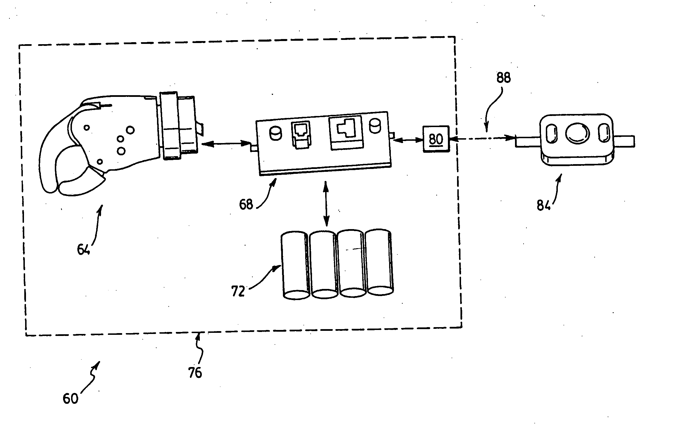
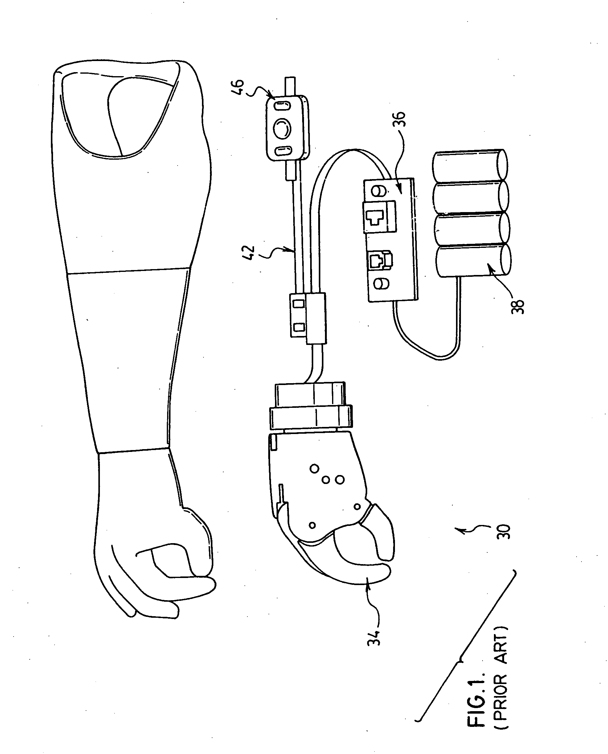
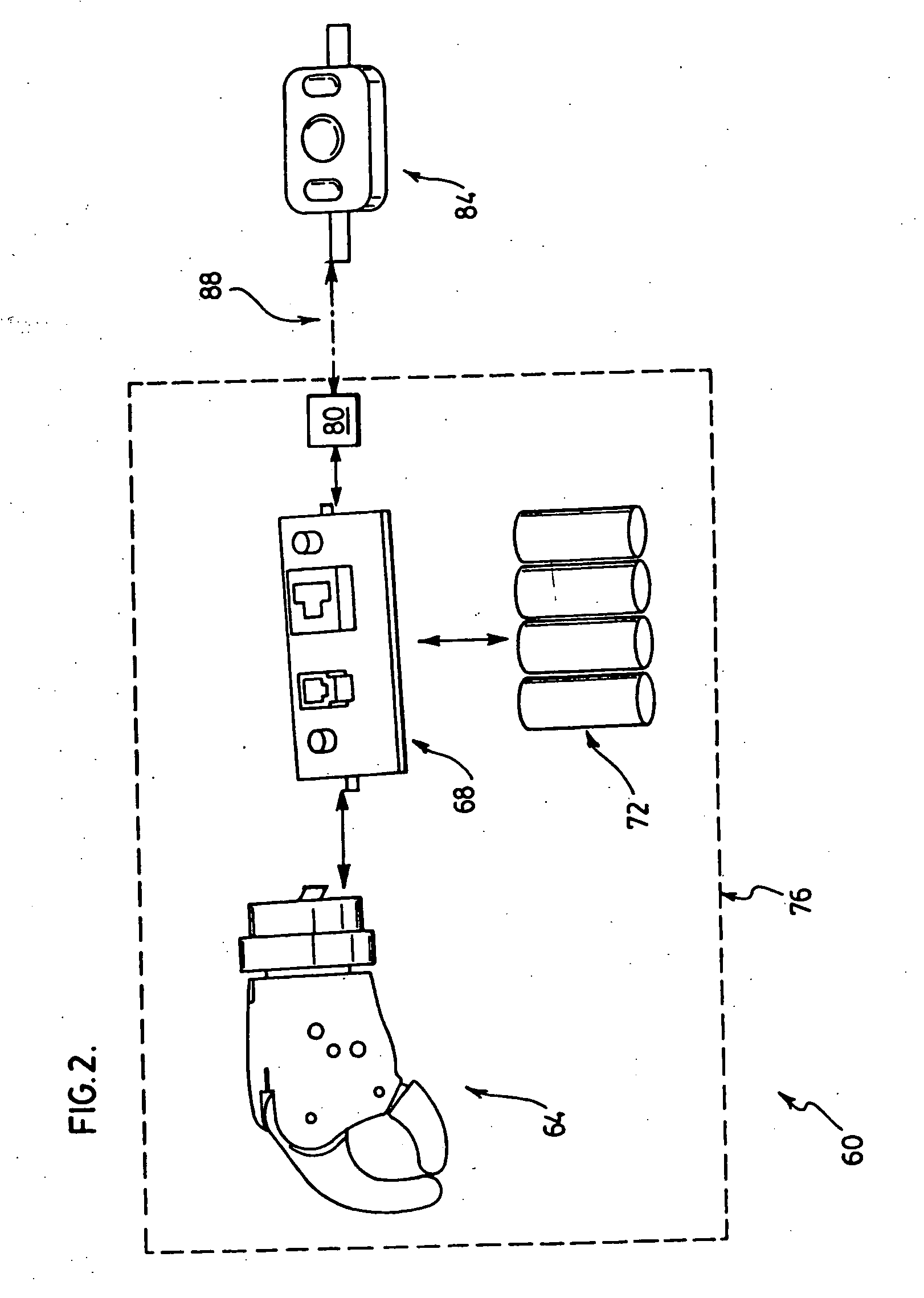
[0033] Referring now to FIG. 1, a prior art prosthetic system is indicated generally at 30. System 30 includes an electromechanical prosthetic limb 34 that is connected to a controller 36 having a separate power supply 38. Controller 36 is connected via a ribbon cable 42 to an electromyographic sensor 46. Sensor 46 is an Otto Bock brand of myographic electrode, model number 13E125. Sensor 46 can be affixed to any tissue on the wearer of limb 34 that can be activated by the wearer so that impulses can be sent to sensor 46 for the purposes of controlling limb 34. Ribbon cable 42 carries power to sensor 46 from power supply 38. Cable 42 also carries signals generated by sensor 46 to controller 36. In turn, controller 36 is operable to interpret such received signals and issue instructions to limb 34 to cause limb 34 to move in a particular fashion. Cable 42 presents certain problems for system 30, in that its length can limit the tissue that can be used by the wearer. As yet a further ...


PUM


Abstract

An electromyographic sensor is provided. The sensor includes electrodes for receiving signals from tissue when the electrodes are placed in contact with the tissue. The sensor also includes circuitry for converting the signals into a format suitable for transmission. the sensor also includes a transmitter for transmitting the signals to a receiver. The receiver can be part of a controller for a prosthetic limb, or the like.

Description

FIELD OF THE INVENTION [0001] The present invention relates generally to control of prostheses and the like and more particularly relates to an electromyographic sensor. BACKGROUND OF THE INVENTION [0002] Electromyographic (“EMG”) sensors are well known. EMG sensors in particular are known for their use in the control of electrically powered prosthetic systems. An individual can have an EMG sensor affixed to a portion of his or her body, and issue instructions to a prosthesis attached to the EMG sensor by voluntarily sending muscular signals to the EMG sensor. The EMG sensor detects the electric signal of the muscles and generates a control or input signal that is delivered to the prosthetic system. In this manner, the user voluntarily controls the prosthesis. One example of a prior art EMG sensor is the Otto Bock brand of myographic electrode (EMG sensor), from Otto Bock, Two Carlson Parkway North, Suite 100, Minneapolis, Minn. 55447-4467, model number 13E125. [0003] Existing EMG s...

Claims


Application Information

Patent Timeline
Patent Type & Authority Applications(United States)
IPC IPC(8): A61F2/70A61B5/04A61B5/103
CPCA61B5/0006A61B5/04888A61F2/68A61F2/72A61F2002/546A61F2002/704A61F2002/705A61F2/70A61B5/389
Inventor WELLS, DAVID L.BISHOP, JOHN W.O'BRIEN, PAUL K.MOMEN, KAVEH SEYED
Owner BLOORVIEW MACMILLAN CHILDRENS CENT
Why Eureka
Try Eureka