Heterogeneous thermal interface for cooling

a heterogeneous thermal interface and cooling technology, applied in the field of thermal interfaces, can solve the problems of thermal runaway, limited chip cooling, and general limited thermal conductivity of conventional pastes

Active Publication Date: 2006-07-20
GLOBALFOUNDRIES US INC
View PDF9 Cites 56 Cited by
  • Summary
  • Abstract
  • Description
  • Claims
  • Application Information

AI Technical Summary

Problems solved by technology

However, the thermal conductivity of conventional pastes is generally limited (e.g., typical pastes have a thermal conductivity of approximately 0.1 W / mK).
Thus, limited chip cooling is achieved.
Furthermore, heavy cycling may cause non-uniform behavior in a paste, or may cause a paste to fail to thermally bond the chip to the heat sink, resulting in thermal run-away and also limiting chip cooling.
Moreover, the trend towards smaller, more powerful chips that generate even greater amounts of heat makes reliance on thermal pastes inadequate.

Method used


Image

  • Heterogeneous thermal interface for cooling
  • Heterogeneous thermal interface for cooling

Examples


Embodiment Construction

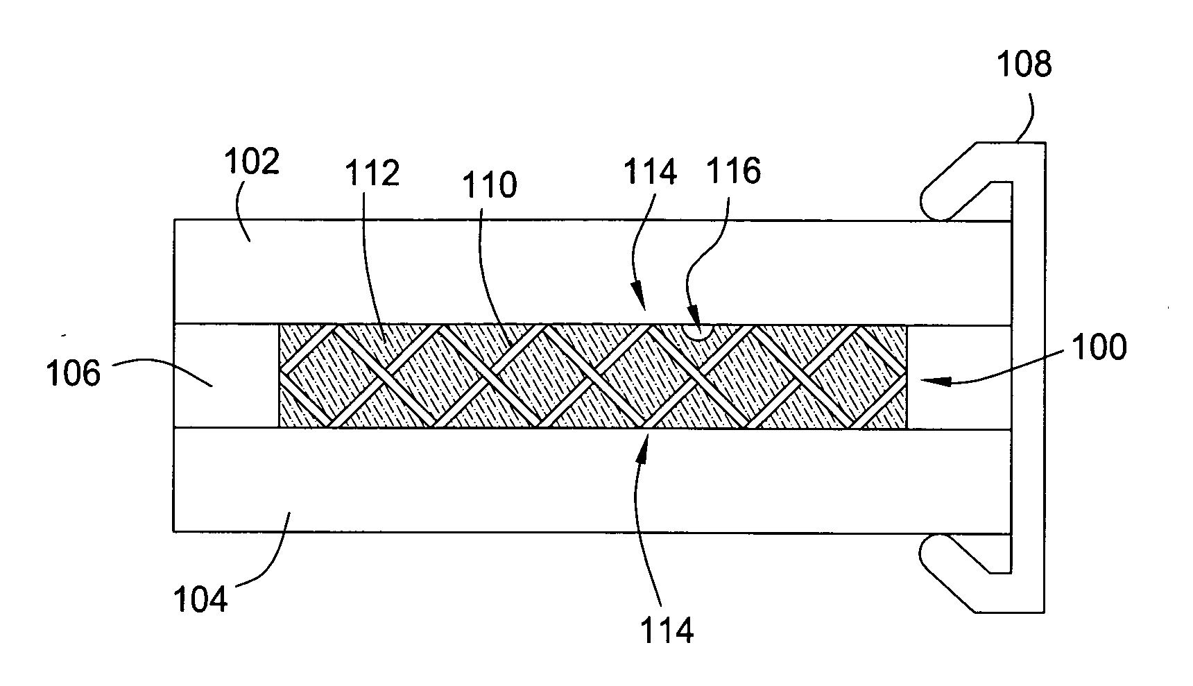
[0013]FIG. 1 depicts a cross-sectional view of one embodiment of a thermal interface 100. The thermal interface 100 is disposed between a heat source 102 and a heat sink 104. The heat source 102 may be any heat source, including but not limited to an integrated circuit (IC) chip. The heat sink 104 may be any heat sink, such as a cold plate of air-cooled fins, water-cooled fins, heat pipes, radiators, thermal spreaders, and the like. The thermal interface 100, heat source 102 and heat sink 104 may be held together in an assembly by any suitable means, such as bonding, adhering, clamping, brackets, fixtures, and the like. In the embodiment depicted in FIG. 1, the heat source 102, the heat sink 104, and the thermal interface 100 are held together by at least one clamp 108.

[0014] The thermal interface 100 is typically formed in the range of from about 50 to about 200 microns thick and generally includes a thermally conductive, heat transfer liquid 112 disposed in a mesh 110. The liquid...


PUM

PropertyMeasurementUnit
thickaaaaaaaaaa
thickaaaaaaaaaa
gap sizesaaaaaaaaaa

Abstract

The present invention is a thermal interface for coupling a heat source to a heat sink. One embodiment of the invention comprises a mesh and a liquid, e.g., a thermally conductive liquid, disposed in the mesh. The mesh and the thermally conductive liquid are adapted to contact both the heat source and the heat sink when disposed therebetween. In one embodiment, the mesh may comprise a metal or organic material compatible with the liquid. In one embodiment, the liquid may comprise liquid metal. For example, the liquid may comprise a gallium indium tin alloy. A gasket may optionally be used to seal the mesh and the liquid between the heat source and the heat sink. In one embodiment, the heat source is an integrated circuit chip.

Description

BACKGROUND [0001] The present invention relates generally to a thermal interface, and relates more particularly to the cooling of integrated circuit chips. Specifically, the present invention relates to a heterogeneous thermal interface for chip cooling. [0002] Efficient cooling of integrated circuit (IC) devices is essential to prevent failure due to excessive heating. As the number of CMOS devices per chip and clock speeds have increased, such efficient cooling has become an even more prominent concern. Efficient cooling of the IC chips depends in large part on a good thermal interface between the chips and cooling blocks, or heat sinks, because a major part of the heat resistance budget is expended between the chip and the heat sink. [0003] Conventionally, the thermal interface between a chip and a heat sink includes a thin layer of thermally conductive paste disposed between opposing surfaces of the chip and the heat sink unit. Typically, the layer of paste is approximately 100 ...

Claims


Application Information

Patent Timeline
Patent Type & Authority Applications(United States)
IPC IPC(8): H05K7/20
CPCH01L23/3733H01L23/4093H01L23/42H01L2924/0002H01L2924/00
Inventor GELORME, JEFFREY D.GUHA, SUPRATIKLABIANCA, NANCY C.MARTIN, YVESVAN KESSEL, THEODORE G.
Owner GLOBALFOUNDRIES US INC
Why Eureka
Try Eureka