Vertical hall effect device

Inactive Publication Date: 2006-07-20
HONEYWELL INT INC
View PDF21 Cites 17 Cited by
  • Summary
  • Abstract
  • Description
  • Claims
  • Application Information

AI Technical Summary

Benefits of technology

[0012] It is, therefore, one aspect of the present invention to provide for improved Hall effect elements and devices thereof.
[0013] It is another aspect of the present invention to provide for improved Hall effect elements and devices, which can be implemented in the context of sensing applications.
[0014] It is yet another aspect of the present invention to provide for an improved vertical Hall effect device capable of being incorporated into an integrated circuit.
[0015] The aforementioned aspects of the invention and other objectives and advantages can now be achieved as described herein. A vertical Hall effect apparatus, including methods thereof, are disclosed. In general, a substrate layer can be provided upon which an epitaxial layer is formed. The epitaxial layer is surrounded vertically by at least one isolation layer. Additionally, an oxide layer can be formed above the epitaxial layer. A plurality of Hall effect elements can be formed within th

Problems solved by technology

Unfortunately, the lack of uniformity of such diffusion can induce an output voltage at zero

Method used


Image

  • Vertical hall effect device
  • Vertical hall effect device
  • Vertical hall effect device

Examples


Example

[0020] The particular values and configurations discussed in these non-limiting examples can be varied and are cited merely to illustrate at least one embodiment and are not intended to limit the scope thereof.

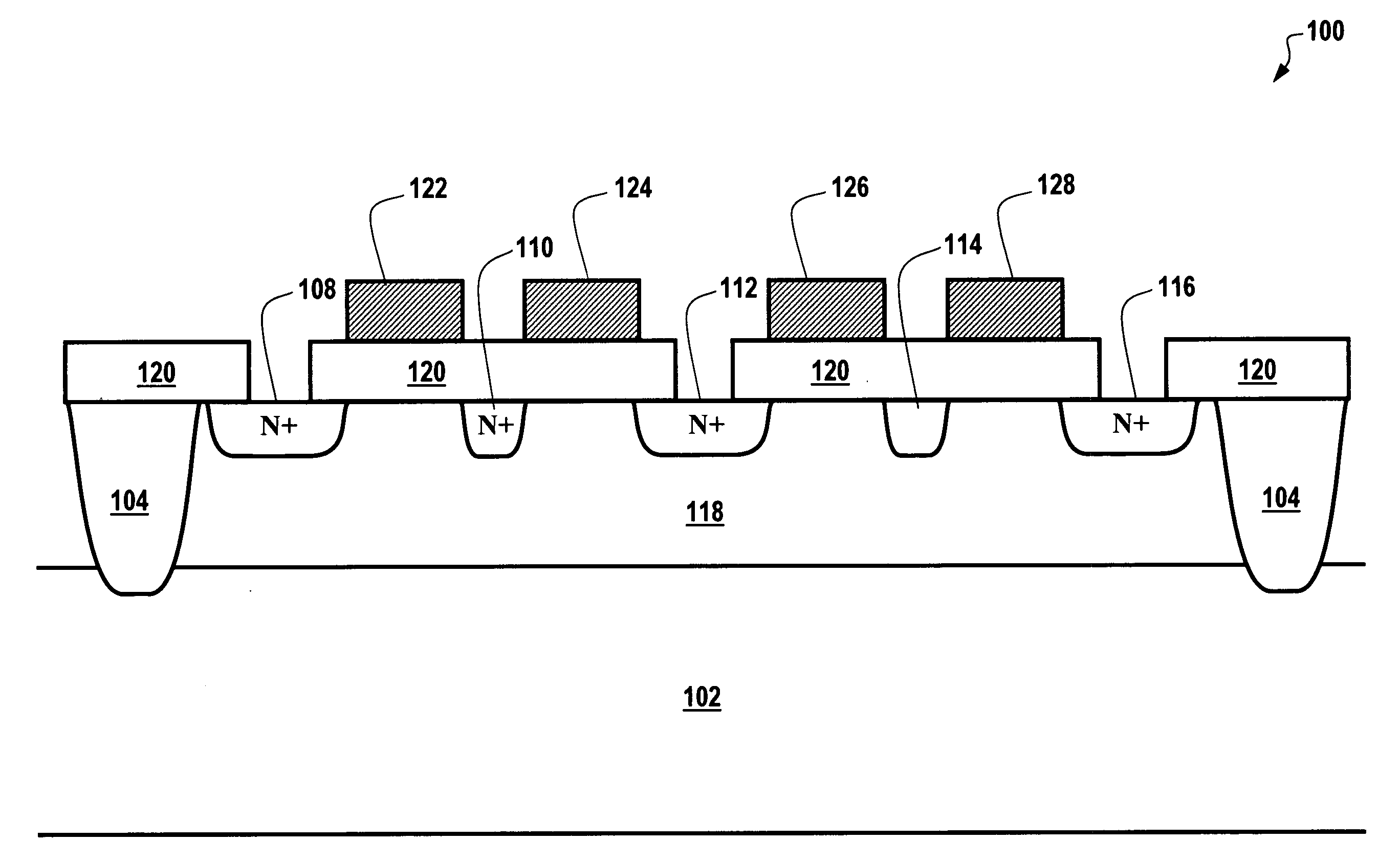
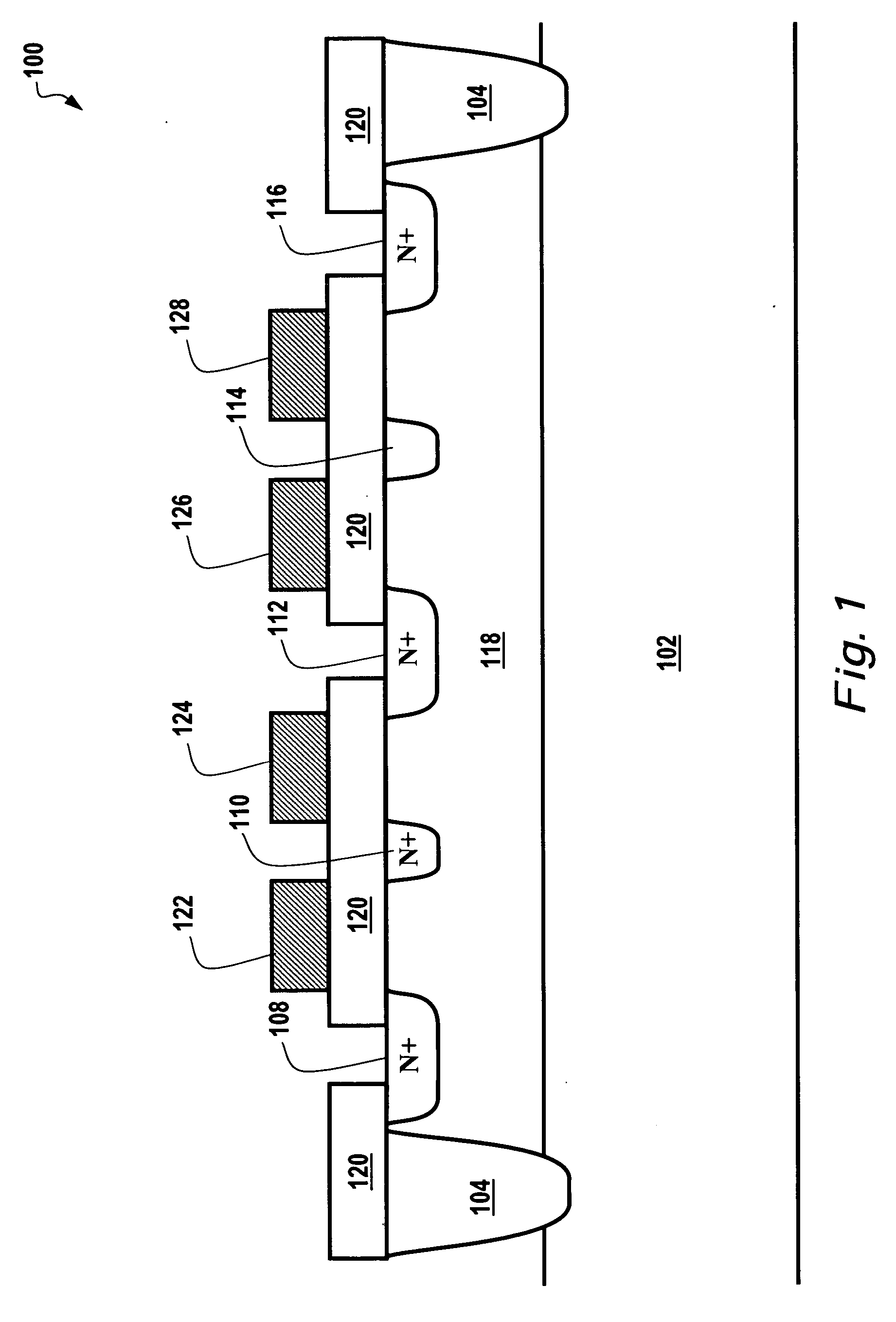
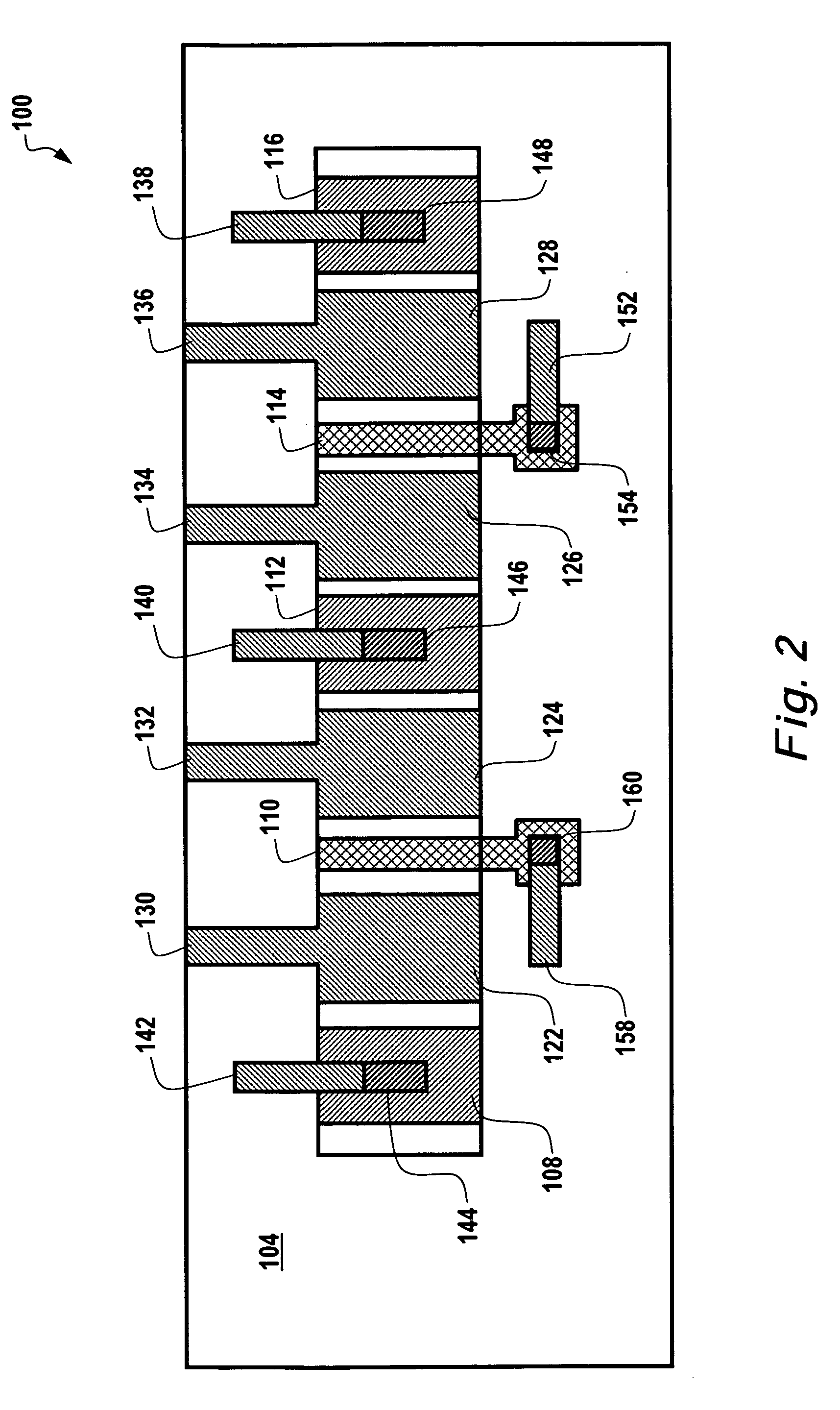
[0021]FIG. 1 illustrates a side view of a vertical Hall effect apparatus 100, which can be implemented in accordance with a preferred embodiment. FIG. 2 illustrates a top view of the vertical Hall effect apparatus 100 depicted in FIG. 1 in accordance with a preferred embodiment. Note that in FIGS. 1-2, identical or similar parts are generally indicated by identical reference numerals. FIGS. 1-2 therefore serve to illustrate varying view of the same vertical Hall effect apparatus 100.

[0022] Apparatus 100 generally includes a substrate layer 102 upon which an epitaxial layer 118 can be formed. An isolation layer 104 surrounds the epitaxial layer 118 vertically. Additionally, an oxide layer 120 can be formed above the epitaxial layer 118. A plurality of Hall effect elements 110...


PUM


Abstract

A vertical Hall effect apparatus, including methods thereof. A substrate layer can be provided upon which an epitaxial layer is formed. The epitaxial layer is surrounded vertically by one or more isolation layers. Additionally, an oxide layer can be formed above the epitaxial layer. A plurality of Hall effect elements can be formed within the epitaxial layer(s) and below the oxide layer, wherein the Hall effect elements sense the components of an arbitrary magnetic field in the plane of the wafer and perpendicular to the current flow in the hall element. A plurality of field plates can be formed above the oxide layer to control the inherited offset due to geometry control and processing of the vertical Hall effect apparatus, while preventing the formation of an output voltage of the vertical Hall effect apparatus at zero magnetic fields thereof.

Description

TECHNICAL FIELD [0001] Embodiments are generally related to Hall effect elements and devices thereof. Embodiments also relate to Hall effect sensors. Embodiments additionally relate to Hall Effect elements and devices capable of being incorporated into an integrated circuit. BACKGROUND OF THE INVENTION [0002] For detecting the position of an object, some transducers exploit the Hall effect, whereby, if a conductor material through which current flows in one direction is immersed in a magnetic field directed perpendicular to the current flow direction, across the sensor an electric field is observed perpendicular to both the current and the magnetic field and proportional to the strength of the magnetic field at that point. [0003] Consequently, with known Hall-effect transducers, by measuring the potential difference across the sensor, it is possible to determine the position of a magnetic element (e.g., a permanent magnet or magnetic circuit) whose field pattern is known. [0004] Hal...

Claims


Application Information

Patent Timeline
IPC IPC(8): H01L43/00H01L29/82
CPCG01R33/077H01L43/065H10N52/101
Inventor ALIMI, YOUSEF M.BIARD, JAMES R.MORALES, GILBERTO
Owner HONEYWELL INT INC
Why Eureka
Try Eureka