

Methods and systems for modulating acoustic energy delivery
a technology of acoustic energy delivery and modulation method, which is applied in the direction of mechanical vibration separation, separation process, laboratory glassware, etc., can solve the problems of limiting reaction applications to non-critical processes, distorted acoustic field, and defocused energy distribution, etc., to achieve safe sample treatment process
- Summary
- Abstract
- Description
- Claims
- Application Information
AI Technical Summary
Benefits of technology
Problems solved by technology
Method used
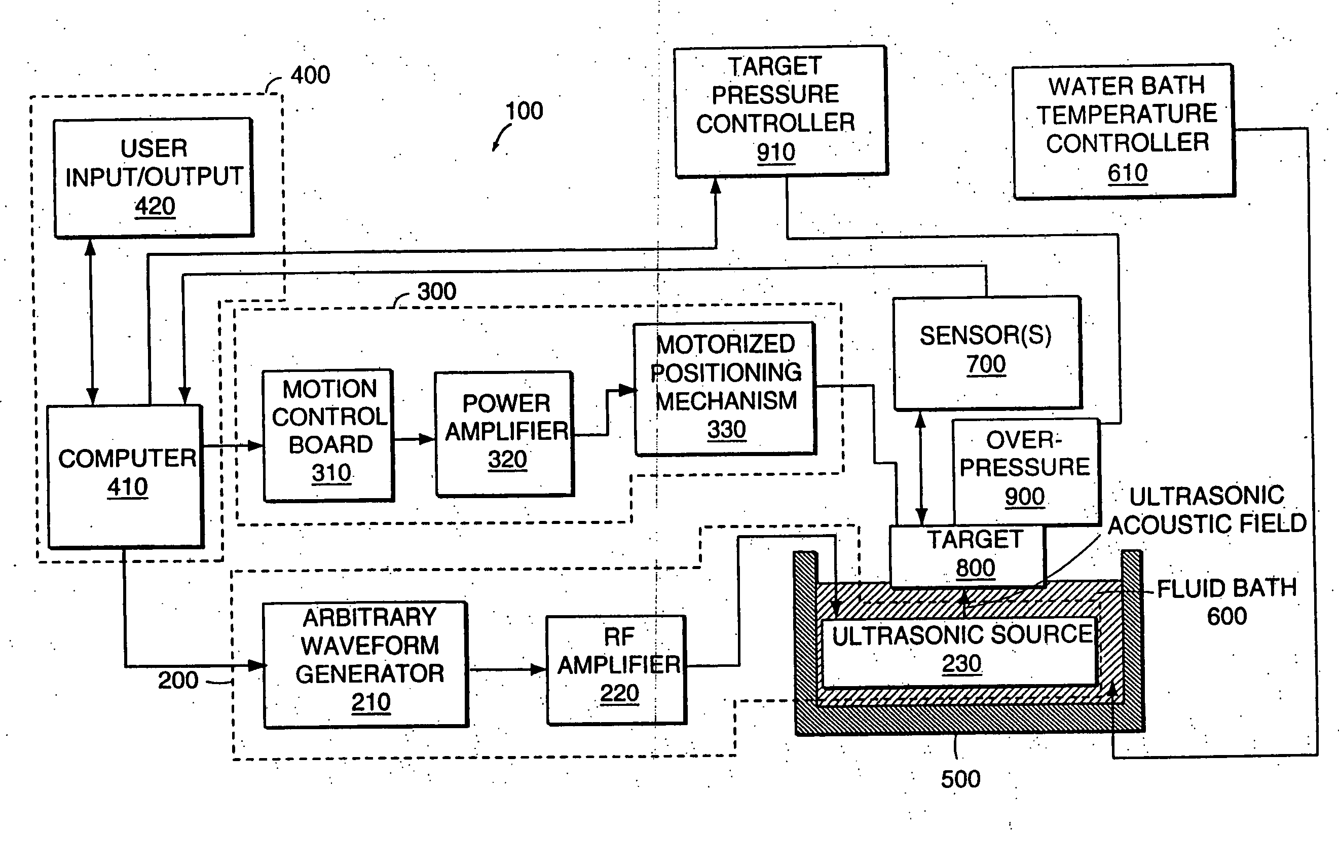
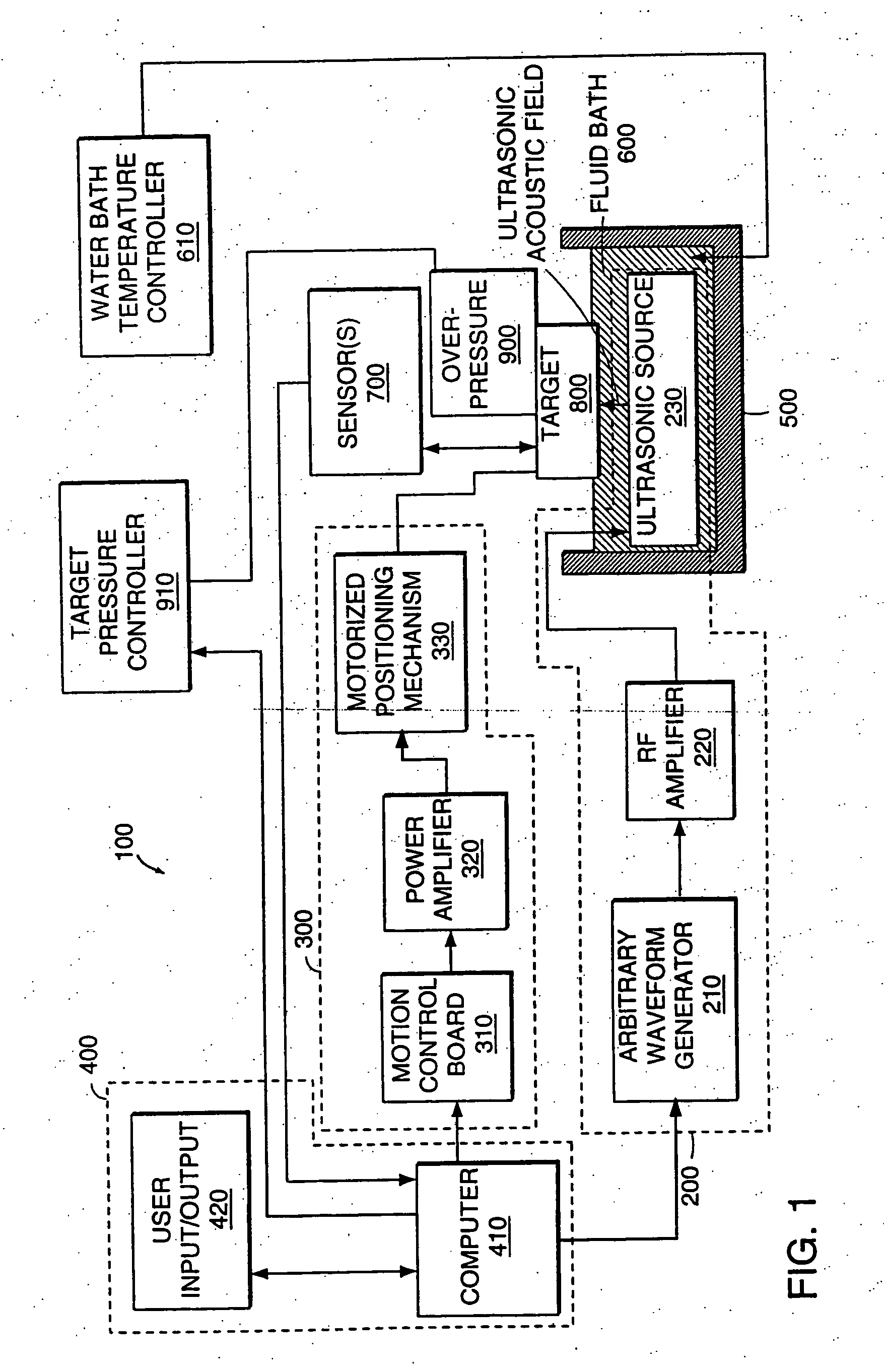
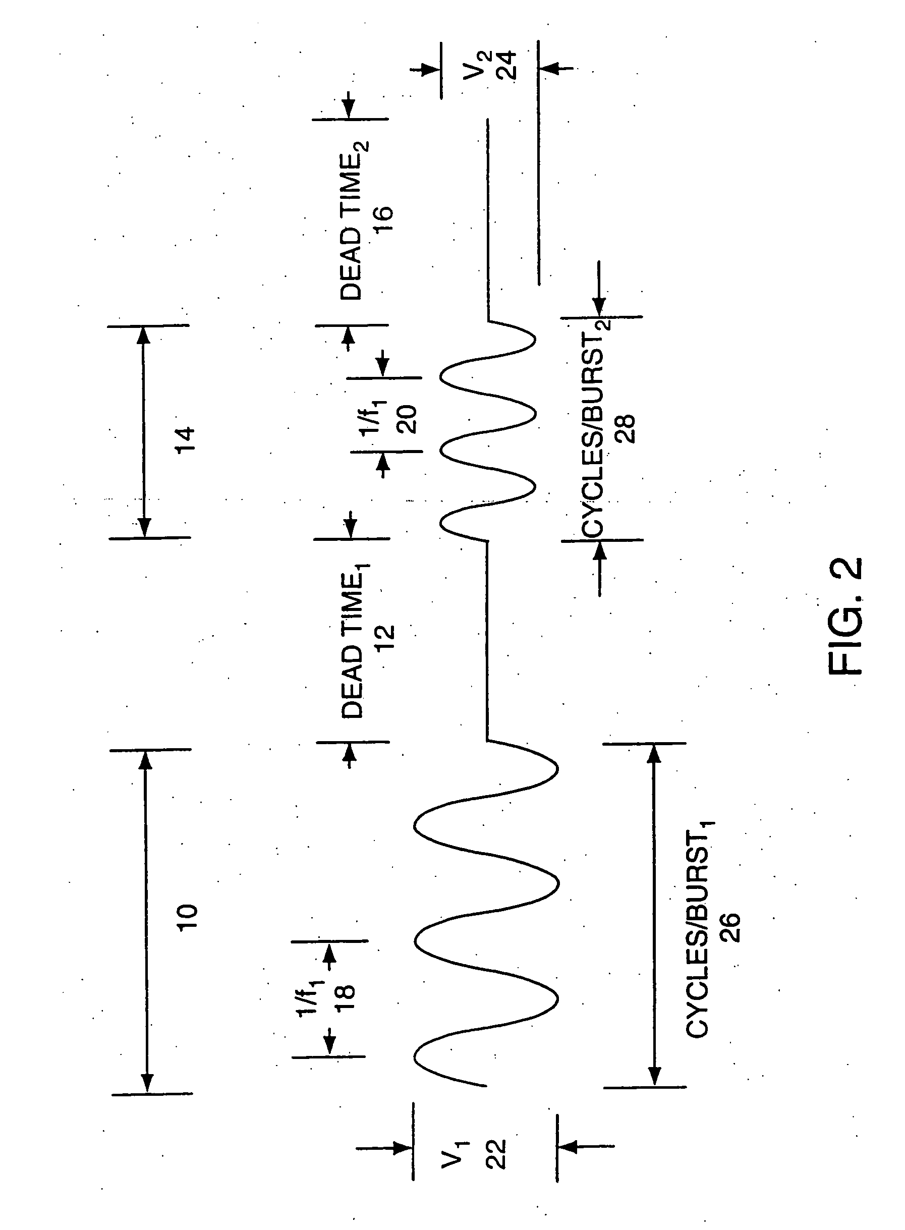
Image

Examples
example 1
Isolation of Intracellular Components from Cells
[0264] To further aid in the understanding of this invention, a procedure for the isolation of intracellular components from cells imbedded in a matrix is described. A sample of about 100 cu. mm. volume is placed into each well of a multiwell plate, such as a 96 well plate, having a capacity of about 200 microliters (200 cu. mm). The entire plate is then frozen and reduced to about minus 40° C. Then, about 100 microliters of an extraction solution, precooled to 4° C., is added to each well while the plate is held at minus 40° C. This maintains the sample temperature at minus 20° C. or less, while providing a smooth surface in the well for coupling to the wave source. A sheet of flexible plastic foil is optionally affixed to the plate to prevent cross contamination between the contents of the wells, or between the wells and the wave source. A piezoelectric wave source is provided and positioned on the plate. The source has 96 pins in t...
example 2
Steady-State Temperature Control with Controlled Waveform Generation to Uniformly Mix a Sample
[0265] In this sample, the duty cycle of an ultrasound treatment was varied to reduce steady-state temperature rise within a sample, compared to a continuous wave, 100% duty cycle.
[0266] A 1.1 MHz high power transducer was applied to a sample treatment vessel. The sample treatment vessel was constructed of two layers of thin film. The bottom consisted of a ⅜ inch (9.5 mm) diameter hemispherical “bubble” from bubble-wrap packing material with the flat side cut away to yield a ⅜ inch diameter hemisphere, made of a thin plastic. The top layer was 0.001 inch thick saran film again, a thin plastic. The vessel, having approximately a 300 .mu.l total volume, contained a liquid sample of 50% methanolic solution, that is 1:1 methanol volume to water volume. The sample treatment vessel was inserted into a frame that allowed the bubble to protrude into the focal zone of the transducer in a water bat...
example 3
Increasing Extraction Output by Using Infrared Temperature Feedback to Vary Either the Duty Cycle and / or the Voltage
[0268] A 1.1 MHz high power transducer was configured to treat a sample in a treatment vessel constructed in a manner as described in Example 2. The acoustic dosage received by a sample of leaf issue suspended in a methanol solution in the vessel was 500 cycles / burst, 2,000 bursts per dose, with a variable duty cycle. The starting temperature of the vessel was less than 1° C.
[0269] Upon initiation of the treatment, the temperature within the vessel stabilized within 10 seconds and remained stable during the dosage interval of up to ten minutes. The duty cycle was adjusted to control the temperature rise. The effect of the dose was visually similar, whether the dose was received by the sample as one long burst in a continuous wave (“CW”) or as an accumulation of shorter bursts, having a duty cycle less than 100%.
[0270] The results are shown graphically in FIG. 8. At ...
PUM
| Property | Measurement | Unit |
|---|---|---|
| Frequency | aaaaa | aaaaa |
| Frequency | aaaaa | aaaaa |
| Temperature | aaaaa | aaaaa |
Abstract
Description
Claims
Application Information