Image processing apparatus and refractive index distribution measuring apparatus

a technology of refractive index distribution and measuring apparatus, which is applied in the direction of phase-affecting property measurement, material analysis, instruments, etc., can solve the problems of high-accuracy measurement, design value cannot be achieved, and important refractive index distribution measurement, etc., and achieve high-accuracy measurement

Inactive Publication Date: 2006-07-20
CANON KK
View PDF2 Cites 21 Cited by
  • Summary
  • Abstract
  • Description
  • Claims
  • Application Information

AI Technical Summary

Benefits of technology

[0007] It is an object of the present invention to provide an image processing apparatus, an image processing program, and a refractive index distribution measuring apparatus, which impose no limitations on the measurement direction of transmitted wavefronts or interference fringes, have resistance to loss of a transmitted wavefront image and noise, and allows production of refractive index distribution data with high accuracy.

Problems solved by technology

The presence of the nonuniform refractive index distribution significantly affects the image-forming ability and the like of the optical element which requires high optical performance, so that design values cannot be achieved.
Based on that fact, the measurement of the refractive index distribution is an important issue and high-accuracy measurement is needed.
In conventional methods, however, only a refractive index distribution obtained from integration in a transmission direction of light is observed, and a three-dimensional refractive index distribution such as an internal distribution cannot be provided.
To determine the three-dimensional distribution, an optical element to be tested must be measured in several parts, for example by slicing it, and high-accuracy measurement is difficult to achieve.
However, the change from interference fringes to transmitted wavefronts involves problems such as an error in a dense part of the interference fringes and a phase jump, and thus accurate transmitted wavefronts cannot be provided in many cases.
Particularly, since the CT analysis used in the method disclosed in Japanese Patent No. 3423486 described above utilizes the Fourier transform, it cannot be performed if the images of transmitted wavefronts have any loss due to the abovementioned problems, an opaque part of the object under test, and the like.
In addition, the measurement direction of the transmitted wavefronts is limited to one orthogonal to the axis around the single axis, so that it is difficult to provide a stable and accurate refractive index distribution.
Furthermore, in the wavefronts changed from the interference fringes, each pixel has a different expected error amount, but the difference in the error amount for each pixel cannot be reflected in the estimation of the refractive index distribution, leading to a reduction in accuracy.

Method used


Image

  • Image processing apparatus and refractive index distribution measuring apparatus
  • Image processing apparatus and refractive index distribution measuring apparatus
  • Image processing apparatus and refractive index distribution measuring apparatus

Examples


embodiment 2

[0075] In an image processing apparatus and an image processing program of Embodiment 2, refractive index distribution data (hereinafter referred to simply as a refractive index distribution) within an object under test is produced directly from an interference fringe image (hereinafter referred to as measured interference fringes) provided by measuring the object under test in a plurality of light ray directions.

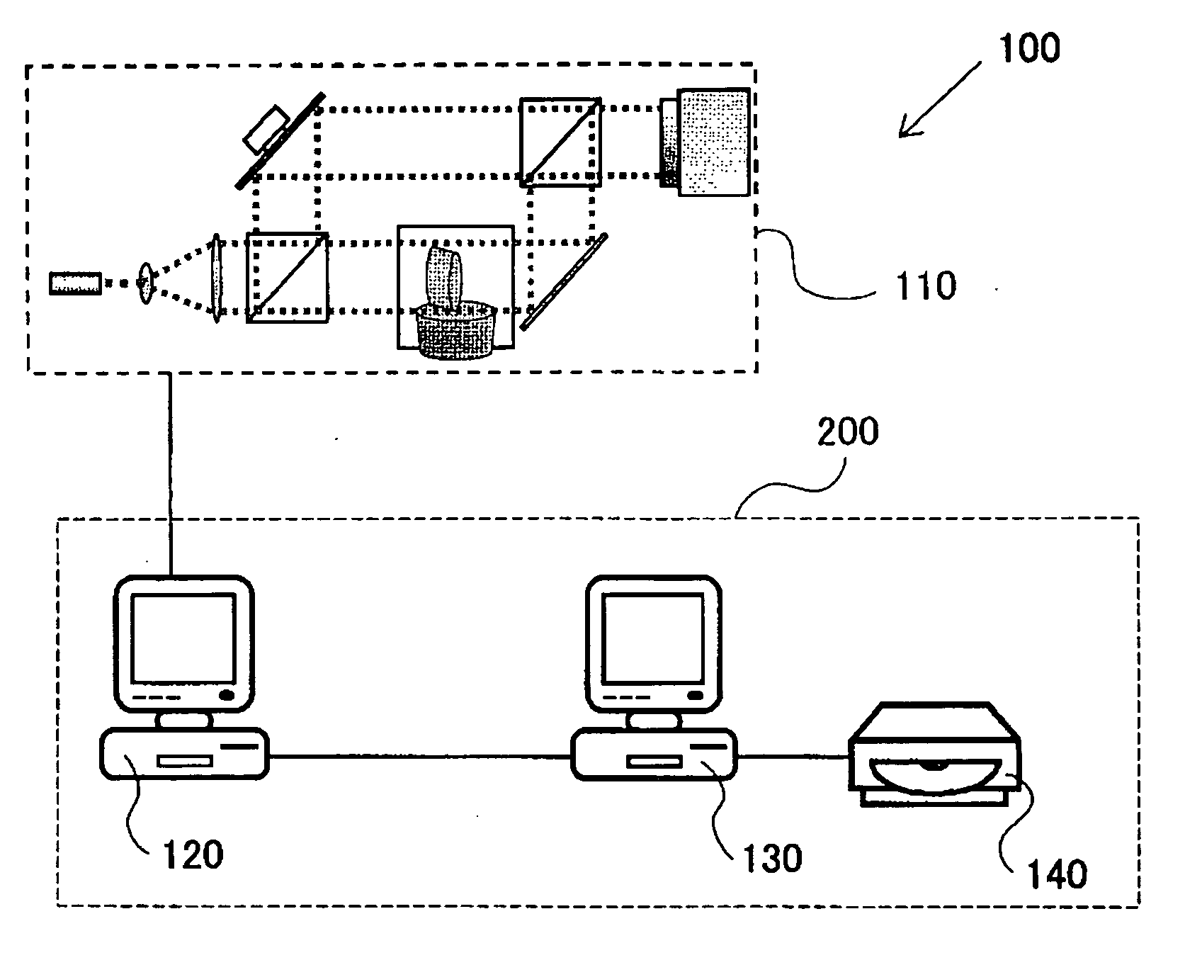
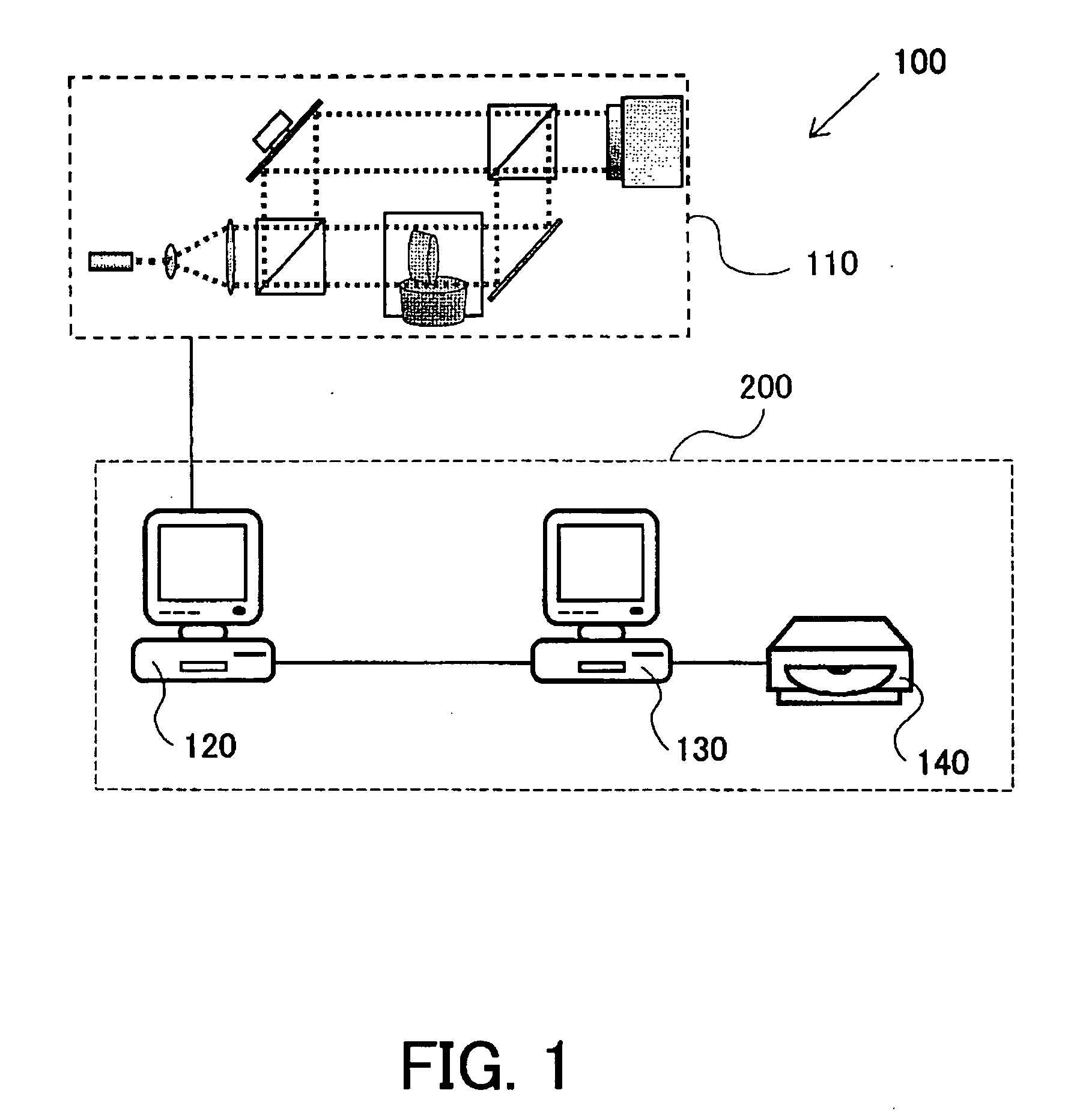
[0076]FIG. 5 shows an example of the structure of a refractive index distribution measuring apparatus 100′ which includes the image processing apparatus and an interferometer of Embodiment 2. The refractive index distribution measuring apparatus 100′ is comprised of an interferometer 110 and an image processing apparatus 200′. The image processing apparatus 200′ is comprised of a refractive index distribution generator 130′ and a refractive index distribution recorder 140. The refractive index distribution generator 130′ is formed of a single personal computer. The respect...

embodiment 1

similarly to

[0097] The abovementioned first and second modification steps S139, S136′, and the convergence determination step S137′ are typically based on an optimization algorithm called the Simulated Annealing. However, the modification step and the convergence determination step based on another optimization algorithm such as a genetic algorithm may also be introduced to provide N with the minimized value of the expression (13).

[0098] Similarly to Embodiment 1, since the final refractive index distribution N output from the refractive index distribution generator 130′ is a relative value of the phase change amount per unit length to the matching liquid, transformation thereof to a refractive index in a standard unit requires the following calculation: N=λ2⁢ ⁢π⁢N+N0(14)

where λ represents the wavelength of the laser light, and N0 represents the refractive index of the matching liquid.

[0099] The refractive index distribution recorder 140 records the final refractive index distri...

embodiment 3

[0101] The image processing method described in Embodiment 2 can be extended to address the case where the object O is made of glass material with partially low transmittance or the phase of reference light is uncertain. An image processing method which addresses these cases will hereinafter be described.

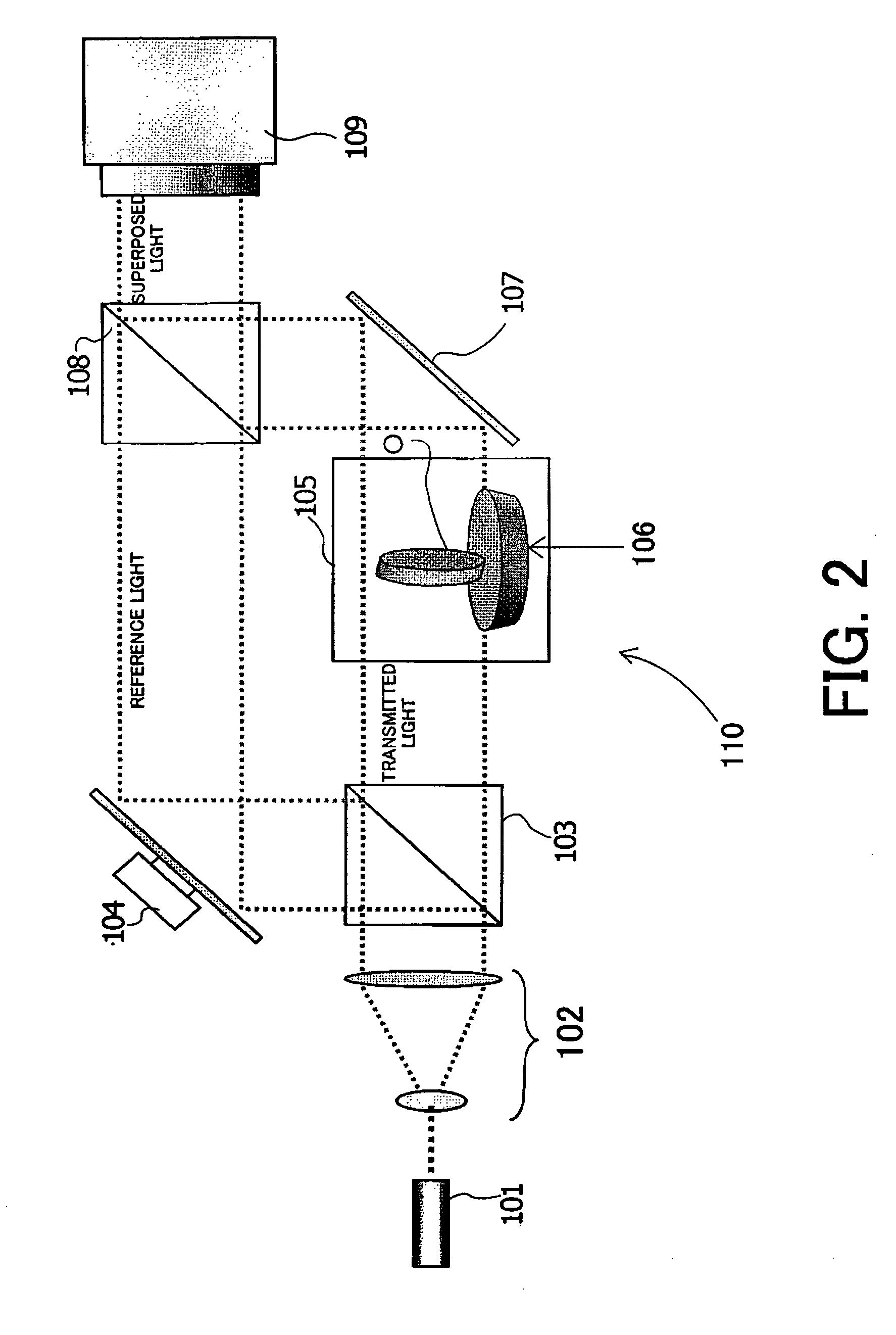
[0102]FIG. 7 shows an example of the structure of a refractive index distribution measuring apparatus 100″ which includes an image processing apparatus and an interferometer of Embodiment 3. The refractive index distribution measuring apparatus 100″ is comprised of an interferometer 110 and an image processing apparatus 200″. The image processing apparatus 200″ is comprised of a refractive index distribution generator 130″ and a refractive index distribution recorder 140. The refractive index distribution generator 130″ is formed of a single personal computer. The respective components which constitute the interferometer 110 and the image processing apparatus 200″ are formed such t...


PUM


Abstract

An image processing apparatus is disclosed which can produce refractive index distribution data with high accuracy without limiting directions in which transmitted wavefronts are measured. The image processing apparatus has a simulating section which simulates a transmitted wavefront in each of the directions to produce a second transmitted wavefront image based on first refractive index distribution data, a comparing section which produces first information indicating the result of comparison between the second transmitted wavefront image and the first transmitted wavefront image, and a changing section which changes the first refractive index distribution data based on the first information to produce second refractive index distribution data. In the apparatus, the processing in the sections is repeated using the second refractive index distribution data as the first refractive index distribution data to produce the resulting second refractive index distribution data which is used as the output refractive index distribution data.

Description

BACKGROUND OF THE INVENTION [0001] The present invention relates to an image processing apparatus and a refractive index distribution measuring apparatus for providing an internal refractive index distribution of an object such as an optical element, and more particularly, to an apparatus for providing an internal refractive index distribution by analyzing a transmitted wavefront or interference fringes. [0002] In recent years, optical elements such as lenses for use in digital cameras and laser-beam printers are often manufactured by molding of optical glass or plastic, and also, optical element shaving aspheric surfaces or free-form surfaces are often manufactured by molding. The molding enables processing of aspheric surfaces at low cost, but produces a nonuniform refractive index distribution within an optical element resulting from a molding time or a molding pressure in manufacture. The presence of the nonuniform refractive index distribution significantly affects the image-fo...

Claims


Application Information

Patent Timeline
Patent Type & Authority Applications(United States)
IPC IPC(8): G06K9/00
CPCG01M11/0228G01N21/45
Inventor SAWADA, YASUHIRO
Owner CANON KK
Why Eureka
Try Eureka