
Multi-carrier transmitting apparatus and multi-carrier transmitting method

a transmission apparatus and multi-carrier technology, applied in the direction of power management, pulse technique, coding, etc., can solve the problem of limiting the improvement of error rate characteristics, and achieve the effect of preventing degradation of transmitting data quality and significantly improving the error rate characteristics of transmitting data

Active Publication Date: 2006-07-20
OPTIS WIRELESS TECH LLC
View PDF14 Cites 82 Cited by
  • Summary
  • Abstract
  • Description
  • Claims
  • Application Information

AI Technical Summary

Benefits of technology

[0006] It is an object of the present invention to provide a multicarrier transmitting apparatus and multicarrier transmitting method that make it possible to improve significantly the error rate characteristics of transmit data for which good quality is required, and prevent degradation of the quality of transmit data for which good quality is required.

Problems solved by technology

However, a problem with a conventional multicarrier transmitting apparatus and multicarrier transmitting method is that, although error rate characteristics can be improved to some extent by combining turbo coding and the OFDM communication method, or turbo coding and the OFDM-CDMA communication method, when simultaneous transmission is performed using a plurality of channels, mutual interference occurs between transmit signals of different channels, and there is a limit to the improvement in error rate characteristics.

Method used


Image

  • Multi-carrier transmitting apparatus and multi-carrier transmitting method
  • Multi-carrier transmitting apparatus and multi-carrier transmitting method
  • Multi-carrier transmitting apparatus and multi-carrier transmitting method

Examples


embodiment 1

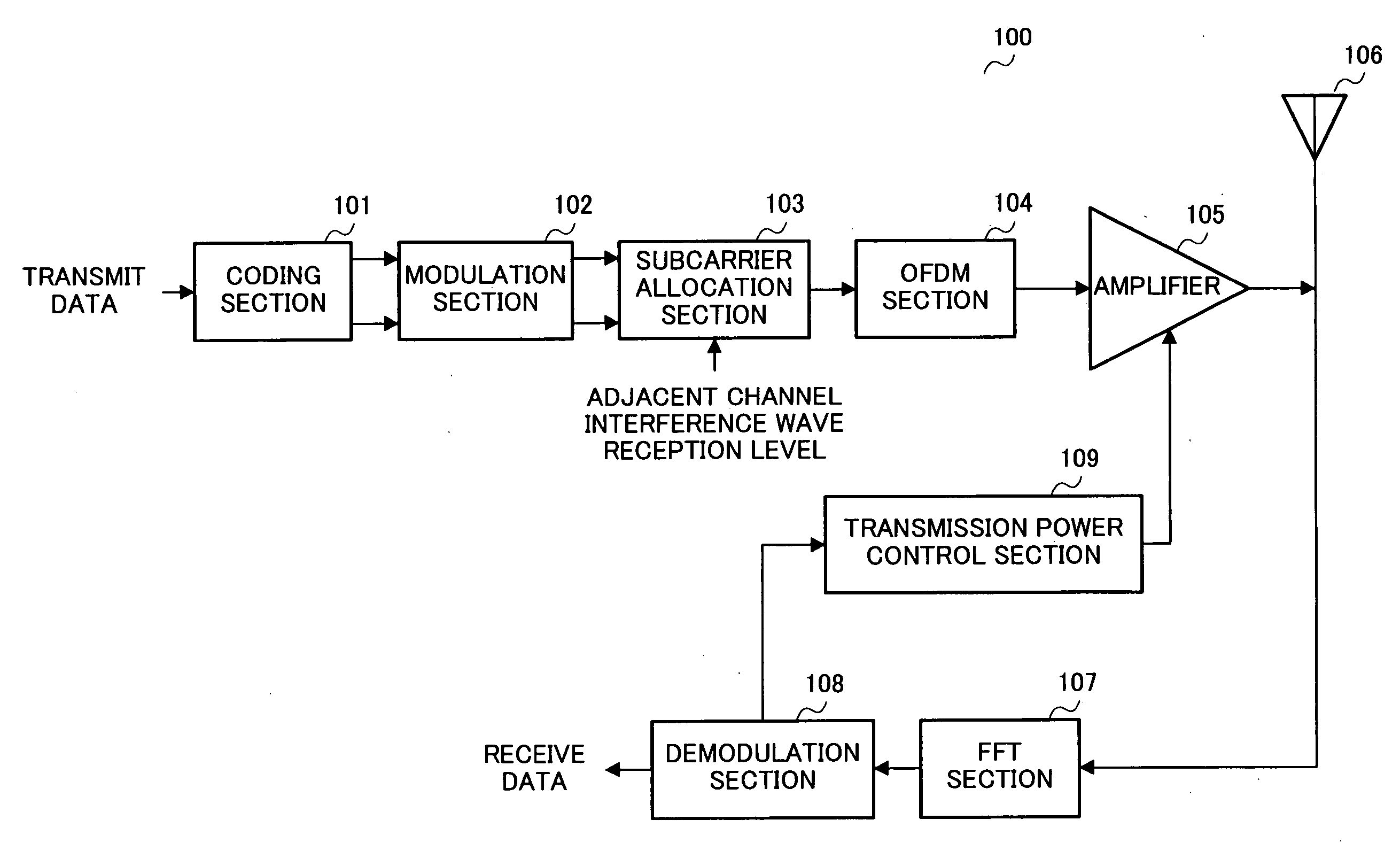
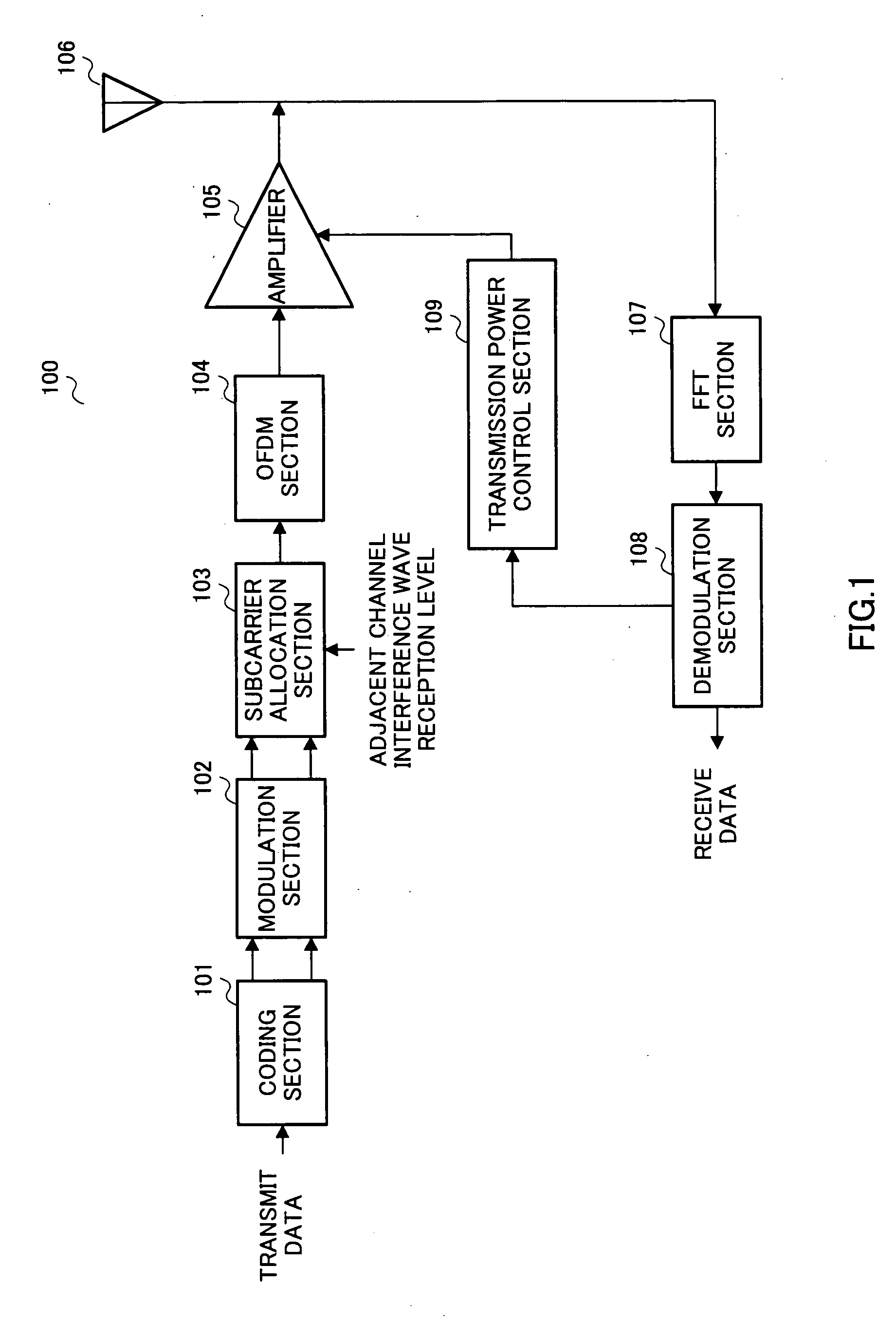
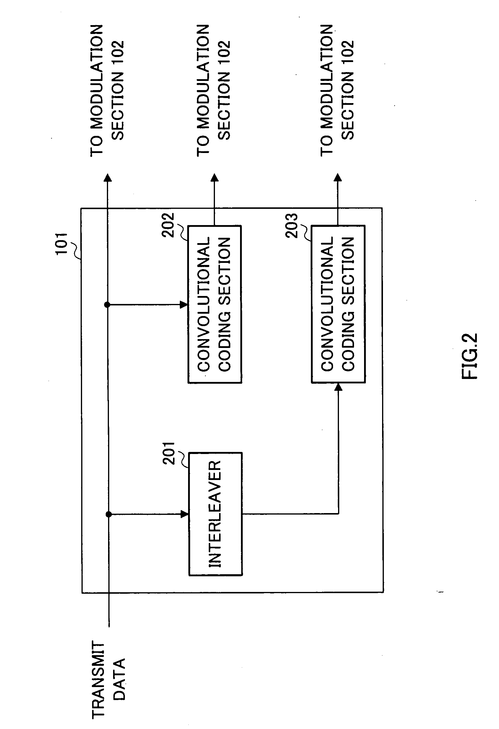
[0030]FIG. 1 is a drawing showing the configuration of a multicarrier transmitting apparatus 100 according to this embodiment, FIG. 2 is a drawing showing the configuration of a coding section 101, and FIG. 3 is a drawing showing transmit data allocation for each subcarrier.

[0031] Multicarrier transmitting apparatus 100 is mainly composed of coding section 101, a modulation section 102, a subcarrier allocation section 103, an OFDM section 104, an amplifier 105, an antenna 106, an FFT section 107, a demodulation section 108, and a transmission power control section 109.

[0032] Coding section 101, which is a dividing section, may be a turbo coder, for example, and outputs part of the input transmit data uncoded to modulation section 102 as systematic bit data, performs recursive convolutional coding on the remaining part of the input transmit data, and outputs this to modulation section 102 as parity bit data. Coding section 101 will be described in detail later herein.

[0033] Modula...

embodiment 2

[0052]FIG. 4 is a drawing showing the configuration of a multicarrier transmitting apparatus 400 according to Embodiment 2 of the present invention, and FIG. 5 and FIG. 6 are drawings showing data allocation for each subcarrier. This embodiment uses a communication method combining CDMA and multicarrier communication.

[0053] A communication method effective for the fourth generation is the OFDM-CDMA communication method combining CDMA and OFDM. The OFDM-CDMA communication method enables interference from other cells to be reduced by means of despreading processing, making it possible for communication to be carried out even when interference from another cell is present, and in this respect differs greatly from OFDM, with which communication becomes totally impossible in the presence of interference waves. In this embodiment, the configuration in FIG. 4 differs from that in FIG. 1 in the provision of a spreading section 401 and despreading section 402. Other component parts in FIG. ...

embodiment 3

[0072]FIG. 7 is a drawing showing the configuration of a multicarrier transmitting apparatus 700 according to Embodiment 3 of the present invention, and FIG. 8 is a drawing showing the configuration of a control section 702. A feature of this embodiment is that turbo code is used as an error correction code, and systematic bit data and parity bit data are adaptively modulated independently.

[0073] In this embodiment, the configuration in FIG. 7 differs from that in FIG. 1 in that a modulation section 701 is composed of a modulation section 701a and modulation section 701b, and control section 702 is provided. Other component parts in FIG. 4 are identical to those in FIG. 1 and are assigned the same codes as in FIG. 1, and descriptions thereof are omitted.

[0074] Control section 702 outputs to modulation section 701a and modulation section 701b control signals specifying modulation methods set based on an RSSI (Received Signal Strength Indicator) signal level. When setting modulation...


PUM


Abstract

A coding section 101 turbo-codes transmit data and outputs parity bit data, and systematic bit data for which good quality is required. A modulation section 102 modulates the parity bit data and systematic bit data. A subcarrier allocation section 103 rearranges the transmit data so that systematic bit data is allocated to subcarriers in the vicinity of the center frequency and parity bit data is allocated to subcarriers in the vicinity of both ends. An OFDM section 104 performs orthogonal frequency division multiplexing of the transmit data, and allocates parity bit data and systematic bit data to respective subcarriers. By this means, it is possible to improve significantly the error rate characteristics of transmit data for which good quality is required, and prevent degradation of the quality of transmit data for which good quality is required.

Description

TECHNICAL FIELD [0001] The present invention relates to a multicarrier transmitting apparatus and multicarrier transmitting method. BACKGROUND ART [0002] Error correction coding methods include turbo coding, which has been adopted as standard in 3GPP. A feature of this turbo coding is that extremely good error rate characteristics can be obtained compared with other error correction methods. [0003] OFDM is an effective communication method for the fourth generation, and is regarded as important as a fourth-generation communication method. On the other hand, since OFDM communication ceases to be possible at all in the presence of interference, the OFDM-CDMA communication method is known that combines CDMA and OFDM and enables communication to be performed even when interference from another cell is present by reducing interference from other cells by means of despreading processing. [0004] Error rate characteristics can be improved by using a combination of turbo coding and the OFDM ...

Claims


Application Information

Patent Timeline
IPC IPC(8): H04B1/04H04B1/02H03M13/29H03M13/37H04J11/00H04B1/707H04J13/00H04L1/00H04L27/26H04W28/18H04W52/24H04W72/04H04W72/08H04W76/02
CPCH03M13/2957H03M13/37H03M13/6325H04L1/0041H04L1/006H04L1/0066H04L1/0071H04L5/0007H04L5/0021H04L5/0037H04L5/0042H04L5/0046H04L5/006H04L5/0064H04L2001/0098
Inventor SUDO, HIROAKI
Owner OPTIS WIRELESS TECH LLC
Learn More