Optical devices and methods for selective and conventional photocoagulation of the retinal pigment epithelium

a technology of optic devices and retinal pigment epithelium, applied in the field of optic devices and methods for applying treatment radiation to the retina, can solve the problems of blind spots, loss of visual sense, and treatment modality that is not suitable for application to the macula

Inactive Publication Date: 2006-07-20
THE GENERAL HOSPITAL CORP
View PDF28 Cites 55 Cited by
  • Summary
  • Abstract
  • Description
  • Claims
  • Application Information

AI Technical Summary

Benefits of technology

[0018] Another aspect of the present invention provides an optical system for applying radiation to the eye of a subject (e.g., a patient). The system includes a source for generating a radiation beam suitable for absorption by RPE cells of the eye. One or more optical components are included in the system for directing the beam onto the eye. The system also includes a scanner optically coupled to the source for moving the beam. The scanner can move the beam along two mutually orthogonal dimensions, each dimension being orthogonal to a propagation axis of the beam. In addition, the system includes a controller for applying control signals to the scanner for adjusting the beam movement. The beam can be moved (scanned) over the retina so as to illuminate one or more retinal locations in a temporal sequence in accordance with one of at least two scan modes.
[0019] In a related aspect of the invention, the controller in the above optical system can apply control signals to the scanner to cause beam movement in accordance with a selected pattern over a selected target area of the retina. The pattern can correspond to illuminating substantially an entire retinal target area requiring treatment, or can correspond to illuminating portions of that target area such that the illuminated portions are separated from one another by non-illuminated portions of the target area.
[0020] In a related aspect of the invention, the scanner in the above optical system can include two beam deflecting devices, one of which is capable of scanning the beam along one dimension and the other is capable of scanning the beam along another dimension (e.g., an orthogonal dimension). Further, the controller can include at least two signal channels, one of which can apply control signals to one of those beam deflecting devices, and another channel can apply control signals to the other. The controller can also include at least two memory modules: one for storing control signals associated with one of those signal channels and the other for storing control signals associated with the other signal channel.
[0021] In another aspect of the present invention, an apparatus is disclosed for applying radiation to the retina, which includes means for generating a radiation beam having one or more wavelengths suitable for absorption by RPE cells, and an optical means for directing the beam to the retina. The apparatus also includes a scanning means, optically connected to the means for generating the radiation beam, for moving the beam on the retina in two dimensions. The apparatus further includes a controlling means that applies control signals to the scanning means for illuminating a plurality of retinal locations in a temporal sequence according to a scan mode. The controlling means can illuminate the retinal locations in at least two scan modes. One of the scan modes can be suitable for selective targeting of the RPE cells, while another scan mode can be suitable for causing thermal coagulation in the retina.
[0022] Another aspect of the present invention is directed to a method for performing photocoagulation. The method includes the step of scanning a continuous wave radiation beam to illuminate one or more retinal locations. The illumination is in a temporal sequence according to a predefined pattern to cause thermal photocoagulation in at least a portion of the retina. The predefined pattern (e.g., an interlaced line pattern) can illuminate substantially all of the retinal target region undergoing photocoagulation. Alternatively, the illuminated location(s) can only be a fraction of the total target region. In the latter instance, the predefined pattern can be, e.g., a separated line pattern.
[0023] A further aspect of the present invention provides a method for performing selective targeting of RPE cells. The method includes the step of scanning a continuous wave radiation beam over the retina so as to illuminate one or more retinal locations in a temporal sequence according to a predefined pattern. The beam's fluence and its dwell time at the illuminated locations are selected so as to cause selective targeting of RPE cells at those locations. The predefined pattern (e.g., a separated line pattern) can mix illuminated areas of RPE cells with nonilluminated areas in a target portion of the retina requiring treatment such that the non-illuminated RPE cells remain undamaged (or at least substantially undamaged) by the illumination process, e.g., by heat deposited in the retina by radiation. Further understanding of the invention can be obtained by reference to the following detailed description in conjunction with associated drawings, which are briefly described below:

Problems solved by technology

The retinal photocoagulation, however, can cause coagulation of photoreceptors, thus leading to blind spots and loss of visual sense.
As such, this treatment modality is not suitable for application to the macula, especially the fovea.

Method used


Image

  • Optical devices and methods for selective and conventional photocoagulation of the retinal pigment epithelium
  • Optical devices and methods for selective and conventional photocoagulation of the retinal pigment epithelium
  • Optical devices and methods for selective and conventional photocoagulation of the retinal pigment epithelium

Examples


example 1

In Vitro Illumination of Bovine RPE Sheets

[0078] The following in-vitro experiments were performed on RPE sheets from young bovine eyes.

Optical Device

[0079] A schematic diagram of the bench top optical device for the in vitro experiments is shown in FIG. 5. A 5 W cw laser (VERDI, Coherent, Santa Clara, Calif., USA) served as a laser source for the illumination. An Argon Ion Laser (INNOVA 90, Coherent) at 488 nm, delivered through a multimode fiber, was used for excitation of the fluorescent cell viability probe as described below. A custom-built compound fluorescence microscope was set up to capture fluorescence images before and after illumination.

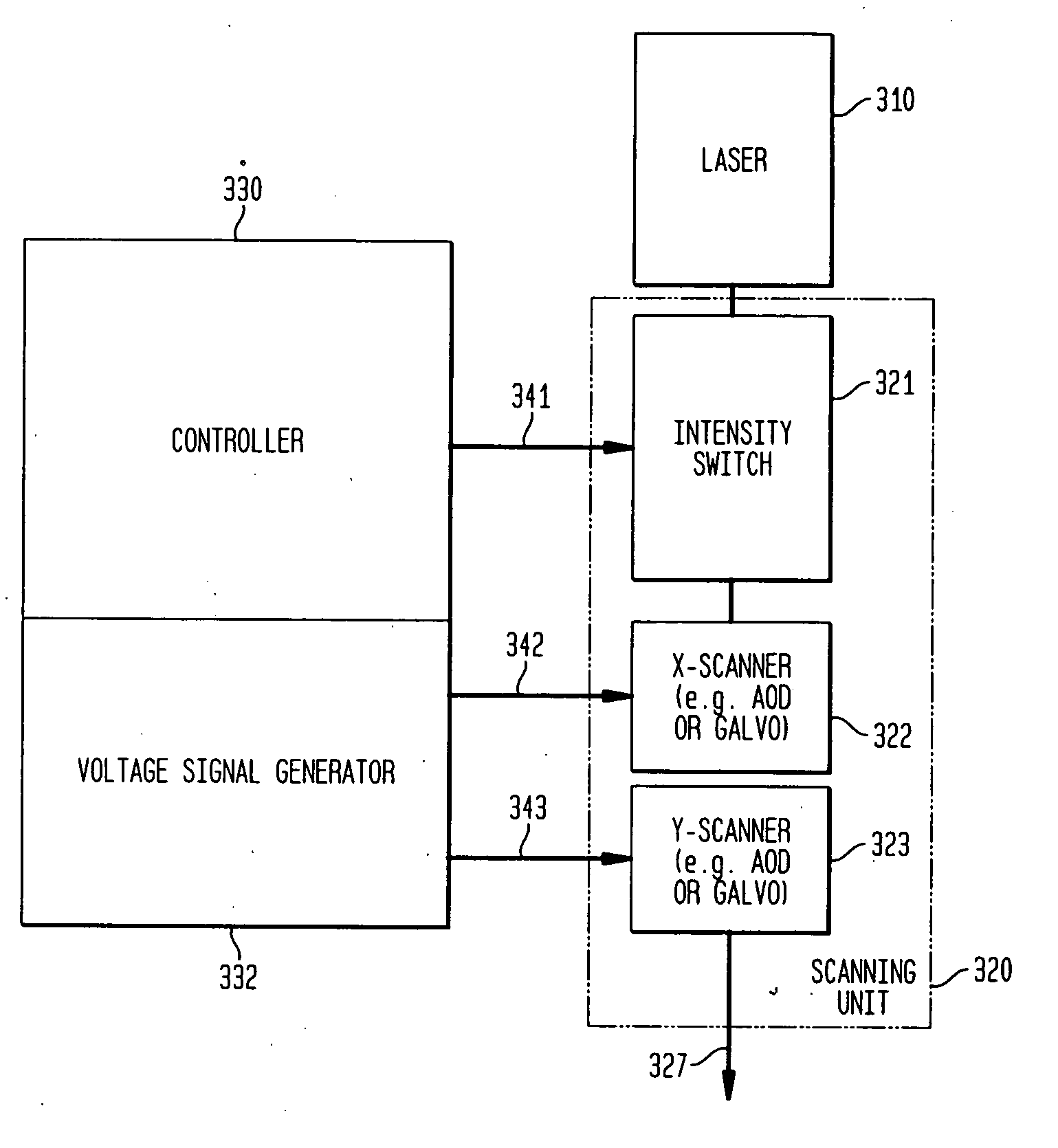
[0080] A two-dimensional (2D) acousto-optic deflector (AOD) was used to generate the scan pattern by mounting two AOD crystals (2DS-100-35-.532, Brimrose, Baltimore, Md., USA) perpendicular to each other to allow two dimensional beam movement. To control the 2D-AOD, four electric signals are needed: one frequency modulation (FM) sign...

example 2

In Vivo Illumination of Rabbit Eyes

[0091] The following in-vivo experiments were performed in rabbit eyes.

Optical Device

[0092] For the in vivo experiments, an optical system was developed to fit on top of a slit lamp as shown in the schematic diagram of FIG. 7. Such a system is considerably smaller than the bench top system utilized with the in vitro experiments. The emission (532 nm) of a cw-laser (VERDI V-10, Coherent) was coupled into a polarization maintaining single mode fiber (PM fiber) (HB450, Fibercore Ltd., UK). PM fiber was employed to preserve diffraction limited beam characteristics and because linear polarization was required for optimal operation of the AOD. Its use limited the power that could be delivered to the setup to about 300 mW. With a typical diffraction efficiency of two AODs (64%) the highest possible power entering the eye was 185 mW.

[0093] A scanner design as utilized in the in vitro experiments was mounted with its mechanical components, collimating ...

example 3

In Vivo Illumination of Rabbit Retina using a SEP Scan Pattern to Achieve Selective Targeting and Thermal Coagulation

[0104] Rabbit retina was illuminated in vivo using a SEP scan pattern to achieve selective targeting in one instance, and thermal photocoagulation in another instance. Histological sections of the irradiated areas were prepared after irradiation to assess the laser-induced damage.

[0105]FIG. 9 presents a histological section of selectively damaged rabbit RPE cells using a SEP scan pattern. The beam had a dwell time of 7.5 μs and a fluence of 470 mJ / cm2, the latter corresponding to about 1.5 times the ED50 fluence. Ten repetitions of the SEP scan pattern were performed. The arrows point to individually damaged RPE cells. The photoreceptors are intact. In contrast, FIG. 10 presents a histological section showing coagulated photoreceptors using a beam dwell time of 30 μs. Ten repetitions were performed using a beam fluence of 1800 mJ / cm2 (about 3 times the ED50 fluence)...


PUM


Abstract

The present invention provides devices and methods for applying radiation to the retina of a patient. In one embodiment, an apparatus includes a radiation source for generating a radiation beam suitable for absorption by retinal pigment epithelial cells. One or more optical components are included to direct the beam onto the retina. A scanner is optically coupled to the radiation source to control movement of the beam in two dimensions to allow a scan over the retina. A controller applies control signals to the scanner to adjust beam movement to illuminate a plurality of retinal locations in a temporal sequence according to a predefined pattern. The device can be operated in one mode to effect selective targeting of retinal pigment epithelial cells, or in another mode to effect thermal photocoagulation of the retina.

Description

RELATED APPLICATIONS [0001] The present application claims priority, as a continuation-in-part application, to a co-pending a U.S. patent application entitled “Selective Photocoagulation,” having Ser. No. 10 / 296,417, as a national phase stage application of a PCT application number PCT / US01 / 17818 filed on Jun. 1, 2001, which, in turn, claims priority to a U.S. provisional patent application entitled “Selective Photocoagulation,” filed on Jun. 1, 2000, and having a Ser. No. 60 / 209,010. All these applications are incorporated herein by reference in their entirety.STATEMENT OF GOVERNMENT SUPPORT [0002] This invention was made with government support under Contract No. F49620-00-1-0179 awarded by AFOSR and Contract No. EY12970-03 awarded by NIH. The government has certain rights in the invention.BACKGROUND OF THE INVENTION [0003] The present invention relates generally to optical devices as well as methods for applying treatment radiation to the eye, and more particularly, to such devic...

Claims


Application Information

Patent Timeline
Patent Type & Authority Applications(United States)
IPC IPC(8): A61B18/18A61B17/00A61B18/20A61F9/008
CPCA61B18/20A61B2017/00057A61B2018/00636A61F9/008A61F9/00821A61F2009/00863A61F2009/00897
Inventor LIN, CHARLES P.ALT, CLEMENS
Owner THE GENERAL HOSPITAL CORP
Why Eureka
Try Eureka