Apparatus and method for connecting a conduit to a hollow vessel

a technology of apparatus and hollow vessel, which is applied in the field of apparatus and method for connecting a conduit to a hollow vessel, can solve the problems of a lack of efficient devices for performing the procedure, and achieve the effect of reducing blood loss

Inactive Publication Date: 2006-07-20
CORREX
View PDF56 Cites 85 Cited by
  • Summary
  • Abstract
  • Description
  • Claims
  • Application Information

AI Technical Summary

Benefits of technology

[0011] An object of the present invention is to provide the necessary surgical tools and prostheses to enable combined percutaneo

Problems solved by technology

The major obstacle to widespread adoption of this superior technique is

Method used


Image

  • Apparatus and method for connecting a conduit to a hollow vessel
  • Apparatus and method for connecting a conduit to a hollow vessel
  • Apparatus and method for connecting a conduit to a hollow vessel

Examples


first embodiment

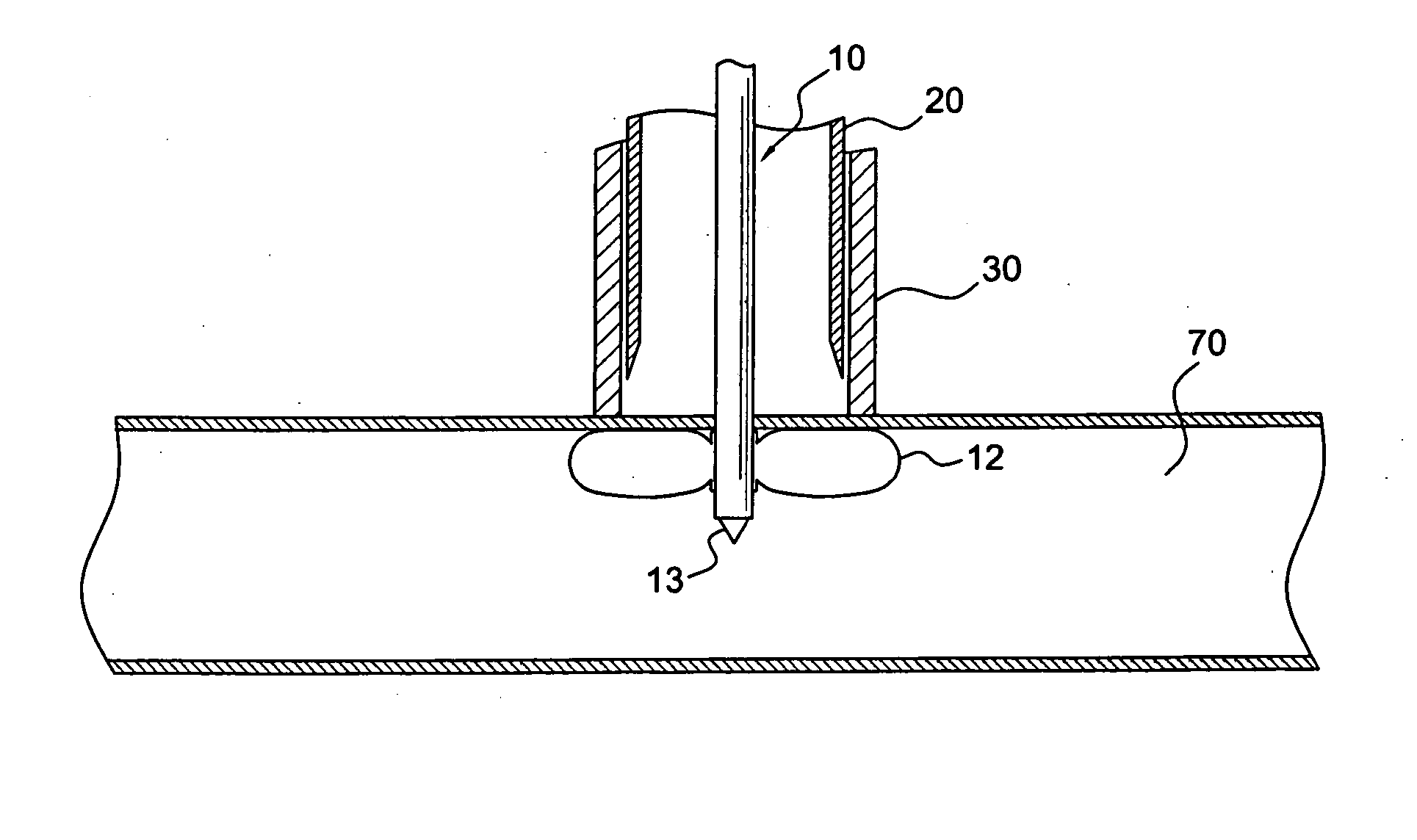
[0050] the present invention is shown in FIGS. 3A to 3I. FIG. 3A illustrates the distal end of the applicator with retractor 10, cutter tube 20, and reaction tube 30. The applicator is shown outside the aorta 70 with balloon 12 deflated. The trocar tool 13 is inserted into the retractor housing 11. (Details of retractor housing 11 and flow passage 15 are shown in FIG. 2D.) Once the desired location where the side branch portion 52 of the aortic connector 50 will pass through the aorta is chosen, the retractor 10 with trocar tube 13 is inserted through the aorta wall and progressed until reaction tube 30 is pressed against the outer wall of the aorta, as shown in FIG. 3B. Then, balloon 12 is inflated. Then, retractor 10 is moved axially with respect to the reaction tube 30 and cutter tube 20 until the aorta 70 is firmly sandwiched between the balloon 12 and reaction tube 30. A spring may be used to move the retractor 10 relative to the reaction tube 30 and to provide the compressive ...

second embodiment

[0060] the present invention is shown in FIGS. 4A to 4H. This embodiment replaces the balloon 12 with a solid clamp pad 17, which is rigidly attached to the distal end of retractor housing 11′. In the alternative, clamp pad 17 itself may be an expansion element, such as a balloon, which a smaller diameter than the cutting element, thereby only allowing it to function as a clamping element. Clamp pad 17 may also include spikes or hooks that penetrate the aortic wall to help prevent movement of the aortic wall relative to the clamp pad 17 after the aortic wall is firmly sandwiched between the clamp pad 17 and reaction tube 30′. Also, the reaction tube 30′ in this embodiment is located concentrically between the cutter tube 20′ and retractor 10′. A description of how the applicator is used to implant the aortic connector 50 will be used to further describe the components of this embodiment.

[0061]FIG. 4A illustrates the applicator with trocar tool 13′ penetrating aorta 70. The trocar 13...


PUM


Abstract

The present invention provides a system and method for forming a side branch on a hollow vessel, such as the aorta. The side branch is preferably adapted to be connected to a connector conduit, but any other suitable use is also acceptable. The system comprises a graft including a side branch portion, and an applicator comprising a hole forming element adapted to form a hole in the wall of the vessel and an insertion element adapted to be inserted through the wall of the vessel, the insertion element comprising a retraction element adapted to enter into engagement with the graft. The hole forming element may comprise a cutting element adapted to cut a hole in the wall of the vessel, and a positioning element adapted to hold the position of the applicator relative to the vessel. The system further comprises a graft protection element adapted to prevent the graft from being damaged by the cutting element. In this case, the clamping element and the graft protection element may be the same element, for example, an expansion element, which may be expandable from an unexpanded state to fully expanded state and to a partially expanded state. The expansion element may be a balloon, which may be in the shape of a circular toroid, and may include a tension member that restricts the dimensions of the balloon. In addition, the expansion element may be an umbrella mechanism.

Description

RELATED APPLICATION DATA [0001] This application is a continuation-in-part of U.S. patent application Ser. No. 11 / 086,577 filed Mar. 23, 2005, and claims priority to U.S. Provisional Patent Application Nos. 60 / 636,449 filed on Dec. 15, 2004, 60 / 726,223 filed Oct. 14, 2005, and 60 / 726,222 filed Oct. 14, 2005, the disclosures of which are hereby incorporated by reference in their entirety.FIELD OF THE INVENTION [0002] The present invention relates to an apparatus and method for connecting a conduit to a hollow vessel, and more particularly, to a surgical device connectable to the aorta to bypass the aortic valve. BACKGROUND [0003] As the average age of the United States population increases, so do the instances of aortic stenosis. An alternative approach to the conventional surgical replacement of the stenotic aortic valve involves the use of an apicoaortic conduit. In this approach, the native aortic valve is not removed, and a prosthetic valve is implanted in a parallel flow arrange...

Claims


Application Information

Patent Timeline
IPC IPC(8): A61B17/34
CPCA61B17/11A61B17/32053A61B2017/00349A61B2017/00557A61B2017/1107A61B2017/00252A61B17/34A61F2/06A61B2017/0061A61F2/064A61B2017/00247A61B2017/1135
Inventor BEANE, RICHARD M.BROWN, JOHN W.CRUNKLETON, JAMES ALANGAMMIE, JAMES S.SMITH, JOSEPH L. JR.
Owner CORREX
Why Eureka
Try Eureka