
Thin film transistor array panel and display device

a technology of thin film transistors and array panels, which is applied in the direction of static indicating devices, non-linear optics, instruments, etc., can solve the problems of increased production costs, complicated operation of data voltage application to data lines, and serious problem of data line signal delay, so as to reduce the number of driving circuit chips and reduce production costs

Active Publication Date: 2006-07-27
TCL CHINA STAR OPTOELECTRONICS TECH CO LTD
View PDF8 Cites 98 Cited by
  • Summary
  • Abstract
  • Description
  • Claims
  • Application Information

AI Technical Summary

Benefits of technology

[0010] The present invention provides a display device which decreases the production cost by reducing the number of driving circuit chips.
[0011] The present invention provides a display device which involves enhanced display image quality.
[0012] The present invention provides a display device which involves enhanced pixel aperture ratio.

Problems solved by technology

However, as the polarity of the data voltage is inverted per predetermined rows and columns, the operation of the application of the data voltage to the data lines becomes complicated, and the problematic signal delay of the data lines becomes serious.
Accordingly, in order to reduce the signal delay, the processing steps are complicated, including the step of forming data lines with a low resistance material, and the production cost is increased.
However, as the column inversion does not involve the advantage of the dot inversion, the display image quality of the LCD is deteriorated due to the vertical flickers and the vertical cross-talks.

Method used


Image

  • Thin film transistor array panel and display device
  • Thin film transistor array panel and display device
  • Thin film transistor array panel and display device

Examples


Embodiment Construction

[0037] The present invention will now be described more fully hereinafter with reference to the accompanying drawings, in which preferred embodiments of the invention are shown. The present invention may, however, be embodied in many different forms and should not be construed as limited to the embodiments set forth herein.

[0038] In the drawings, the thickness of layers, films and regions are exaggerated for clarity. Like numerals refer to like elements throughout. It will be understood that when an element such as a layer, film, region or substrate is referred to as being “on” another element, it can be directly on the other element or intervening elements may also be present. In contrast, when an element is referred to as being “directly on” another element, there are no intervening elements present.

[0039] Now, thin film transistor array panels and LCDs according to embodiments of the present invention will be specifically explained with reference to the accompanying drawings.

[...


PUM


Abstract

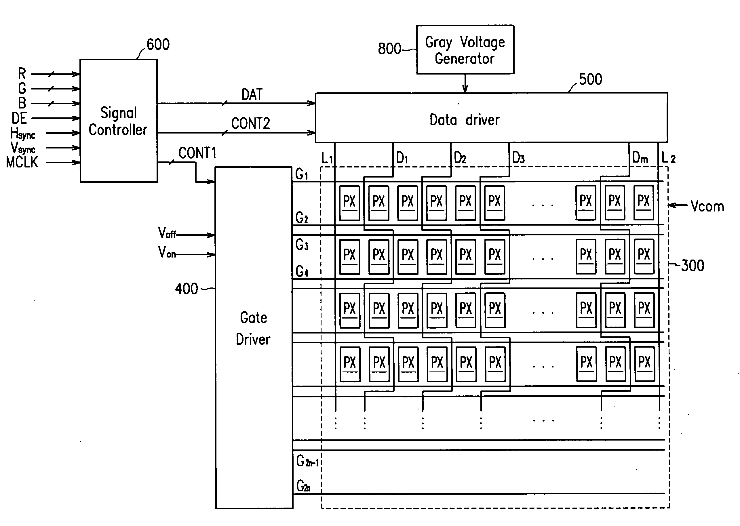
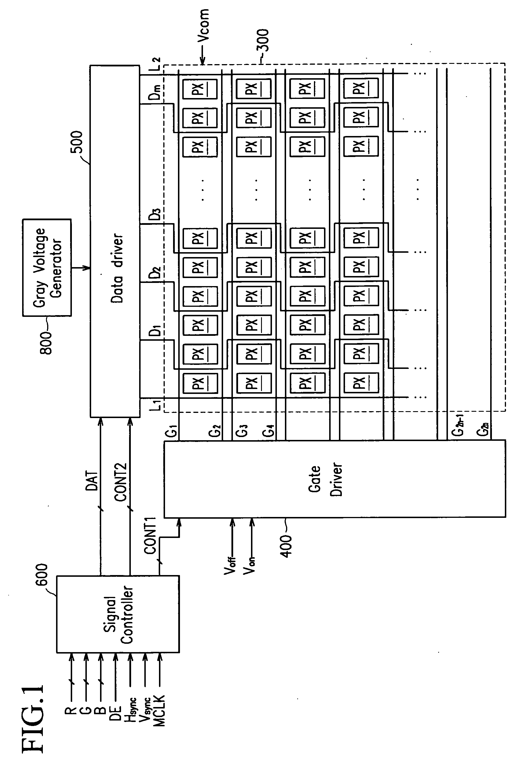
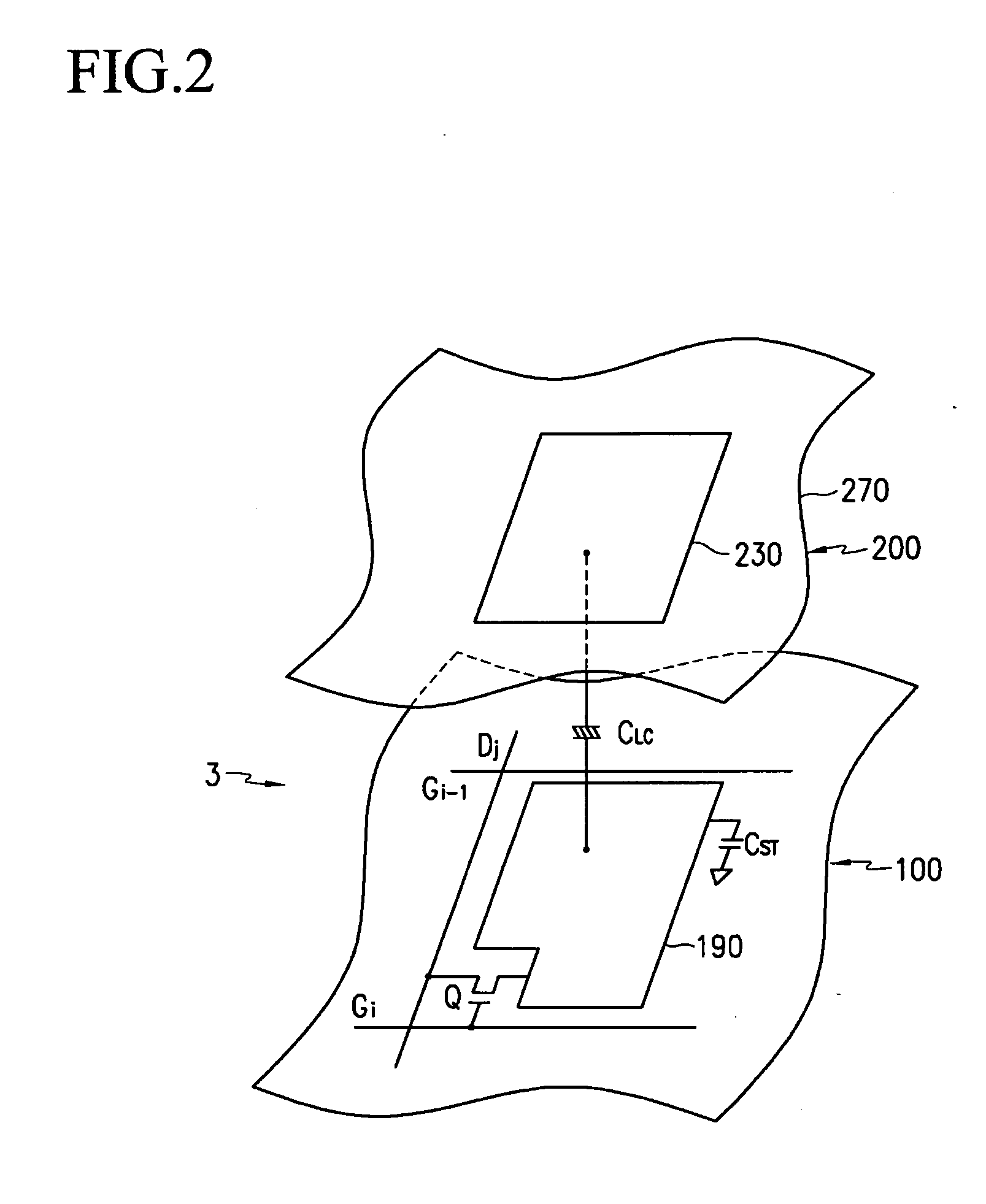
Disclosed is a thin film transistor array panel. The panel includes a plurality of pixels arranged in the form of a matrix each with a pixel electrode and a switching element connected to the pixel electrode, and a plurality of gate lines connected to the switching elements and extending in the row direction. A pair of the gate lines are connected to pixels in each pixel row. A plurality of data lines are connected to the switching elements, and elongated in the column direction. Each data line is provided between two columns of the pixels. The respective data lines are horizontally bent between the two adjacent gate lines, and vertically extend between the two pixel rows.

Description

BACKGROUND OF THE INVENTION [0001] (a) Field of the Invention [0002] The present invention relates to a thin film transistor array panel, and a display device. [0003] (b) Description of the Related Art [0004] Generally, a liquid crystal display (LCD) includes two panels with pixel electrodes and a common electrode, and a liquid crystal (LC) layer disposed between the two panels with a dielectric anisotropy. The pixel electrodes are arranged in the form of a matrix, and connected to switching elements such as thin film transistors (TFTs) to sequentially receive data voltages per the respective rows. The common electrode is formed on the entire surface of the panel to receive a common voltage. From the circuit perspective, the pixel and the common electrodes and the LC layer disposed between those electrodes form an LC capacitor, which basically forms a pixel together with a switching element connected thereto. [0005] Voltages are applied to the two electrodes to form an electric fiel...

Claims


Application Information

Patent Timeline
Patent Type & Authority Applications(United States)
IPC IPC(8): G09G3/36
CPCG02F1/1345G02F2201/40G09G3/3614G09G3/3648G09G2300/0426G09G2300/0443G02F1/133
Inventor KIM, SUNG-MANLEE, SEONG-YOUNGKIM, BEOM-JUNMOON, SEUNG HWANKONG, HYANG-SHIK
Owner TCL CHINA STAR OPTOELECTRONICS TECH CO LTD
Learn More