Low profile holographic sight and method of manufacturing same

a holographic sight and low-profile technology, applied in the field of low-profile holographic sights for firearms, can solve problems such as occupying, and achieve the effect of quick and easy focus

Active Publication Date: 2006-07-27
EOTECH LLC
View PDF17 Cites 75 Cited by
  • Summary
  • Abstract
  • Description
  • Claims
  • Application Information

AI Technical Summary

Benefits of technology

[0011] In one embodiment the laser diode and its electronic control board are mounted on the body using conventional fasteners which are inserted into apertures in the board. These apertures are elongate in the direction parallel to the path of the light beam to allow for a linear adjustment of the board and, thus, the laser diode, in order to focus the reticle pattern. The connections which provide power from the battery to the laser control module include a pair of conductive elements which interconnect the power source and the control board via contact of each of...

Problems solved by technology

Thus, each unit may be quickly and easily focused during assembly, taking up an tolerance ...

Method used


Image

  • Low profile holographic sight and method of manufacturing same
  • Low profile holographic sight and method of manufacturing same
  • Low profile holographic sight and method of manufacturing same

Examples


Embodiment Construction

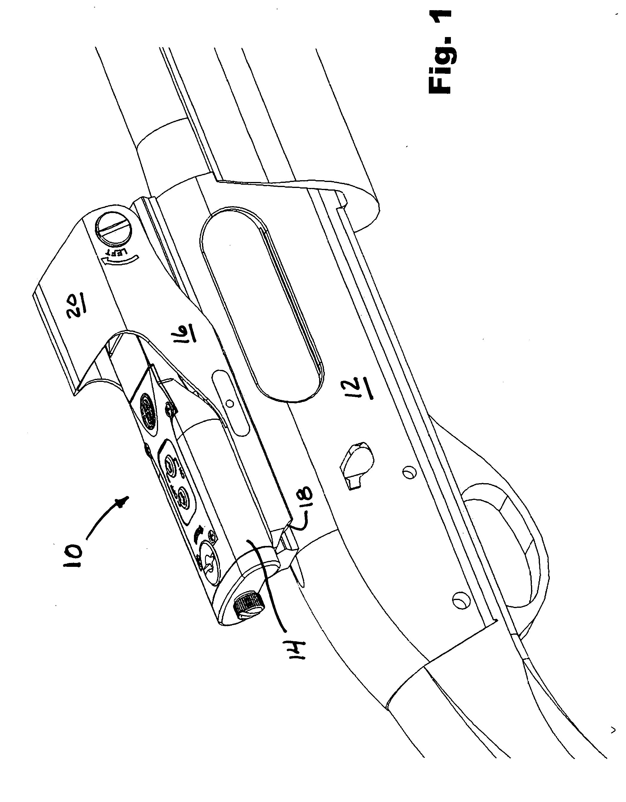
[0026] Referring to FIG. 1, one embodiment of the low profile holographic sight of the present invention, generally indicated by 10, is shown mounted on a shotgun 12, though it will be appreciated that the sight 10 may be similarly mounted for use on other arms, including, for example, rifles, relatively large handguns, and bows. This sight is, however, particularly suited for mounting and use with rifles and shotguns due to its low profile design. The sight 10 includes a body 14 which houses the laser diode, the diode control, the power source, and the optical components, and a base 16 upon which the body of the sight is secured and which, in turn, releasably secures the sight to the firearm. The base includes a mounting mechanism 18 for mounting the sight on the firearm with which the sight is to be used. Of course, various types of mounts may be employed as the mounting mechanism 18 on the sight 10 depending upon the type of weapon, including a standard shotgun mount, a Weaver® m...


PUM


Abstract

A low profile holographic sight includes a base having a mounting mechanism and a body mounted on the base for housing a laser diode, an associated electronic control and power source, and optical elements including a collimator, a transmission image hologram of the reticle pattern, and a reflective diffraction grating, wherein the optical elements are arranged within the body to direct and fold the laser beam in a substantially generally horizontal path, and is insensitive to drift in laser wavelength. The optical elements superimpose an image of the reticle pattern over the direct view of the target scene in a generally parallel and close relationship with the barrel of a firearm, such as a shotgun or a rifle, upon which the sight is mounted.

Description

BACKGROUND OF THE INVENTION [0001] 1. Field of the Invention [0002] This invention relates to low profile holographic sights for firearms. [0003] 2. Background Art [0004] There are several types of sights utilized with firearms, such as rifles, shotguns, handguns and other hand-held weapons, such as bows, including sights which including holographic images of one, two, or three dimensional reticle patterns. [0005] U.S. Pat. No. 5,483,362, issued to Tai et al., describes a sight that is relatively compact. [0006] U.S. Pat. No. 5,815,936, issued to Sieczka et al., discloses a detachable hologram assembly and windage / elevation adjustment mechanism for such a sight. [0007] U.S. Pat. No. 6,490,060, issued to Tai et al., discloses another lightweight compact sight that has a relatively shorter profile, which is particularly advantageous for mounting and use with smaller handguns and some bows. Various embodiments of the holographic sights disclosed in these patents have been sold in the c...

Claims


Application Information

Patent Timeline
IPC IPC(8): G02B5/32
CPCF41G1/30G02B5/32G02B23/14
Inventor SIECZKA, ERIC J.TAI, ANTHONY M.FISH, ROBERT H.
Owner EOTECH LLC
Why Eureka
Try Eureka